If you are going to create a mirror image of a 3D object relative to a line lying in the XY plane, you can still use the MIRROR command. Otherwise, you need to use the 3DMIRROR command, which creates a reflection of objects relative to the plane.
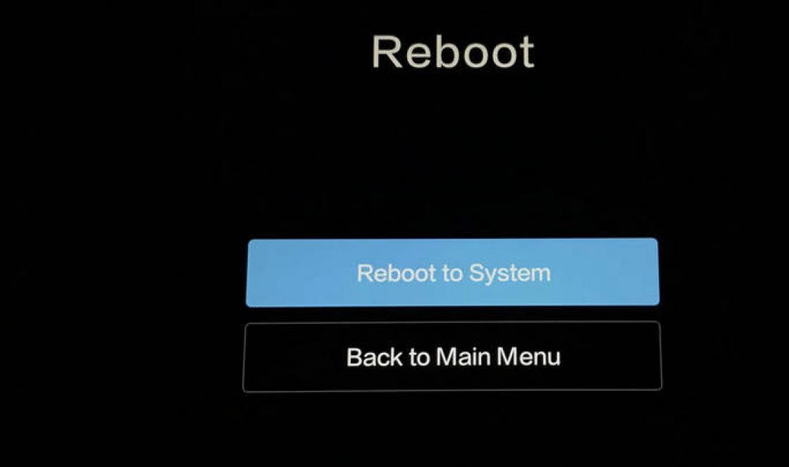
In Fig. Figure 11.14 shows an object obtained by mirroring one object relative to another.
Rice. 11.14. Using the 3DMIRROR command
To create a mirror copy of an object, click the button 3D Mirror(3D mirror)
in the group Modify(Editing) tab Note(Main) ribbon or execute a menu command Modify? 3D Operations? 3D Mirror(Editing? 3D operations? 3D mirror).
A prompt will appear:
Select objects:
Select the objects for which you want to create a mirror copy. If you select objects before calling the command, the program will immediately display the following prompt:
Specify first point of mirror plane (3 points) or<3points>:
At this prompt, AutoCAD prompts you to define the mirror plane using one of the following methods.
Using the Object parameter, you can select an object in the drawing that will serve as a reflection plane.
The Last parameter returns the last mirror point used.
The Zaxis parameter allows you to define the reflection plane by specifying some axis Z by specifying two points belonging to a given axis. Reflection in this case occurs relative to the plane XY, which is perpendicular to a given axis Z.
The View parameter defines a cutting plane passing through the specified point and parallel to the current view.
The XY, YZ and ZX parameters allow you to define a plane parallel to the planes XY,YZ And ZX respectively, and passing through a given point.
The 3points option, selected by default, creates a reflection plane from three specified points.
In response to the question Delete source objects?
DOVECOTE: Dialectics as a reflection of seasonal movements Author: Sergei Golubitsky “I understood almost nothing. And most importantly, I didn’t understand what computers had to do with it. I think if this article had not existed, the world would not have lost much.” User "Ramses" on the Computerra forum addressed to
From the book AutoCAD 2009 author Orlov Andrey AlexandrovichMirroring If you want to create a mirror image of a 3D object about a line in the XY plane, you can still use the MIRROR command. Otherwise, you must use the 3DMIRROR command, which creates a reflection
From the Photoshop book. Multimedia course author Medinov OlegReflection When working with the Reflection tool, pixels that fall within the brush's area of effect are mirrored. It would be best if you try to experiment with this tool yourself and see how it works. Maybe,
From the book AutoCAD 2009 for students. Self-instruction manual author Sokolova Tatyana YurievnaMirroring Objects The MIRROR command mirrors objects. Is it called from the Modify drop-down menu? Mirror or by clicking the Mirror icon on the Modify toolbar. MIRROR command prompts: Select objects: – select objects Select objects: – press Enter
From the book AutoCAD 2009. Let's get started! author Sokolova Tatyana YurievnaMirroring Objects The MIRROR command mirrors objects. Is it called from the Modify drop-down menu? Mirror or by clicking on the Mirror icon on the Modify toolbar. MIRROR command prompts: Select objects: – select objects Select objects: – press the Enter key
From the Photoshop book. Best filters author Bondarenko SergeyExample. Mirroring objects Mirror a part relative to the vertical axis without deleting the old object (Fig. 11.4). Rice. 11.4. Mirroring objectsRun the MIRROR command by calling it from the Modify ? Mirror or by clicking the Mirror icon on
From the book Server Data Storage Technologies in Windows environment® 2000 Windows® Server 2003 by Dileep NaikMirroring relative to a plane The MIRROR3D command, which mirrors objects relative to a given plane, is called from the Modify ? 3D Operations? 3D Mirror.MIRROR3D command requests: Select objects: – select objectsSelect objects: – press the Enter key
From the book Programming in Ruby language[Ideology of language, theory and practice of application] by Fulton HalTile & Mirror (Mosaic and reflection) This group includes a variety of distorting effects that allow you to reflect and scale the picture in different ways. For example, you can create a kaleidoscopic image different types(Kaleidoscope filters), offset effects (XYOffsest)
From the book AutoCAD 2009. Training course author Sokolova Tatyana Yurievna9.4 Local and Remote Mirroring Mirroring was already mentioned in Section 9.1, but was not discussed in detail. Mirroring is the process of creating a duplicate of available data, thereby ensuring data availability when
From the book AutoCAD 2008 for students: a popular tutorial author Sokolova Tatyana Yurievna1.4.2. Reflection The Smalltalk, LISP, and Java languages implement (to varying degrees of completeness) the idea of reflective programming - the active environment can interrogate the structure of objects and expand or modify them at runtime. The Ruby language has extensive support
From the book Firebird DATABASE DEVELOPER'S GUIDE by Borri HelenMirroring Objects The MIRROR command mirrors objects. Is it called from the Modify drop-down menu? Mirror or by clicking the Mirror icon on the Modify toolbar. Command Queries
From the book IT security: is it worth risking the corporation? by Linda McCarthyMirroring relative to a plane The MIRROR3D command, which mirrors objects relative to a given plane, is called from the Modify? 3D Operations? 3D Mirror.Command Requests
From the book Digital photography. Tricks and effects author Gursky Yuri AnatolievichMirroring Objects The MIRROR command mirrors objects. Is it called from the Modify drop-down menu? Mirror or by clicking on the Mirror icon on the Modify toolbar. MIRROR command prompts: Select objects: – select objectsSelect objects: – press Enter to
From the author's bookReflecting attacks The Firebird 1.0.x code contains a large number of string copy commands that do not check the length of the data being copied. Some of these overflows can be exposed to external manipulation by passing large strings of binary data in SQL statements
From the author's bookChapter 1 Deflecting Attacks Detecting, isolating, and resolving incidents is much like disarming explosive devices—the faster and better you do it, the less damage a security incident will cause to your system. Gene Schultz, Chief
From the author's book14.8. Spectacular reflection in water This example refers to the classic effects implemented in Photoshop. What this means, first of all, is that the result of the work in this case is known. It is especially common to see a sports car reflected in the water. We will also go along
So, we use an existing object, which represents the outline of the left wall of a small cabinet in the drawing, to create on its basis using the tool Mirror image exactly the same object, which is a mirror image of the first.
Tool Mirror image allows you to create copies of symmetrically located drawing elements relative to the mirror axis, defined by two points. Since the accuracy of the display depends on the correct choice of the axis, it is very important to have a good idea of what kind of result you want to get. In some cases where the advantage of mirroring is obvious, you can even draw a guide line to make it easier to select the endpoints of the mirror axis. But in our case, this will not be necessary, since the mirror image axis is already present in the drawing. However, to visualize it we will need to use the new object snap mode.
1. Click on the button Mirror image toolbars Change or select the command from the menu Edit » Mirror or enter the command in the command window Mirror.
2. When prompted to select objects, click on the outline of the left side wall of the small cabinet and press Enter to complete the selection. A prompt appears in the command window First point of the reflection axis:.
3. Click the button Middle toolbars Object snap. The object snap to midpoint mode will turn on (AutoCAD will automatically enter the command in the command window _mid). In this mode, AutoCAD can recognize the midpoints of objects.
4. Move the crosshair pointer to the middle of one of the vertical lines indicating the outline of the façade of the small cabinet. Once AutoCAD recognizes the center of the line, a triangular marker will appear on the screen. Click to capture the coordinates of that point.
5. A prompt will appear in the command window Second point of the reflection axis:, and a reflected image of the original object will appear in the drawing, which will move in accordance with the movement of the mirror image axis, the position of which is determined by the first selected point and the current position of the crosshair pointer. 6. Re-enable tethering mode Middle and select the middle of the second vertical segment of the contour of the facade of the small cabinet (Fig. 4.52).

Rice. 4.52 Displaying a side wall relative to an axis passing through the midpoints of the vertical segments of the facade
7. The reflected image will disappear and a prompt will appear in the command window Delete source objects [Yes/No]:. This request means that before the command completes Mirror can delete the original object, leaving only its mirror copy in the drawing. In this case, we don't need it, so press Enter to abort the deletion.
8. A mirror image of the right wall of the small cabinet will appear in the drawing, and the command Mirror will complete its work.
To complete the drawing, we only have a little work left to do: create the contours of the side walls of the cabinet system unit and a large cabinet, the outline of the facade of the large cabinet and the contours of three cutouts in the facades of the small and large cabinets, as well as the table drawer (these cutouts will contain mortise handles). In addition, you need to complete work on the contours of the shelves located in the left corner working area(see Fig. 4.1–4.3). Now you are quite ready to solve the last problem, so we will start with it.
Before you start drawing, make sure that dynamic input is turned on.
We build a rectangle (half of the left part of the entire part). To do this, activate the “Rectangle” tool and click on the screen to indicate the lower left corner of the rectangle (you can also vice versa, the upper right corner), then enter the relative Cartesian coordinate of the opposite corner - 70,120, Enter.
Draw lines inside the rectangle. We move the cursor to the upper left corner of the rectangle, the “end” anchor appears, without clicking we indicate the direction to the right, enter 45, Enter from the keyboard, indicate the direction down, enter 30, Enter from the keyboard, indicate the direction to the right, enter 25, Enter, Enter from the keyboard .
We move the cursor to the lower left corner of the rectangle, the “end” anchor appears, without clicking we indicate the direction to the right, enter 50, Enter from the keyboard, indicate the direction up, enter 90, Enter, Enter from the keyboard.
Round the upper left corner of the rectangle. Turn on the "Match" tool, in command line Check the mode of the "crop" option. If the mode is "WITH CUT" - everything is in order, if not - right-click, select the "Crop" option, select "With crop". Right-click, select the "Radius" option, specify a radius of 30, Enter, build a mate. Click on one side, click on the second side.
Turn on the "Crop" tool, click on the edge of the shape, Enter, click on right side shapes, side is deleted, Enter. Select everything, activate the Mirror tool, click on the bottom right point of the shape, then on the top right point, Enter.
Turn on the "Crop" tool, click on the edge of the right side of the shape, Enter, click on the right side of the shape, the side is deleted, Enter.
Turn on the "Polyline" (or "Segment") tool, snap to the lower right corner of the figure, indicate the direction down, enter 20 from the keyboard, Enter, indicate the direction to the right, enter 55 from the keyboard, Enter, indicate the direction up, enter 90 from the keyboard, Enter, indicate the direction to the left, enter 5 from the keyboard, Enter, indicate the direction up, enter 120 from the keyboard, Enter, indicate the direction to the left, enter 30 from the keyboard, Enter, indicate the direction down, enter 100 from the keyboard, Enter, move the cursor to the left of the right the upper corner of the figure, before the “end” anchor appears, click Enter.
Turn on the "Polyline" (or "Segment") tool, snap to the lower right corner of the figure, indicate the direction to the right, enter 15, Enter, Enter from the keyboard.
Turn on the "Polyline" (or "Segment") tool, snap to the upper right corner of the figure, indicate the direction to the right, enter 20, Enter, Enter from the keyboard.
Select everything, activate the Mirror tool, click on the bottom right point of the shape, then on the top right point, Enter.
The exercise is completed.
|
Add a comment
Name: Email: Spam protection: one thousand six hundred ninety two(number):* |