This device, meter ESR-RLCF, collected four pieces, they all work great and every day. It has high measurement accuracy, has software zero correction, and is easy to set up. Before this, I assembled many different devices on microcontrollers, but all of them are very far from this. You just need to pay due attention to the inductor. It should be large and wound with as thick a wire as possible.
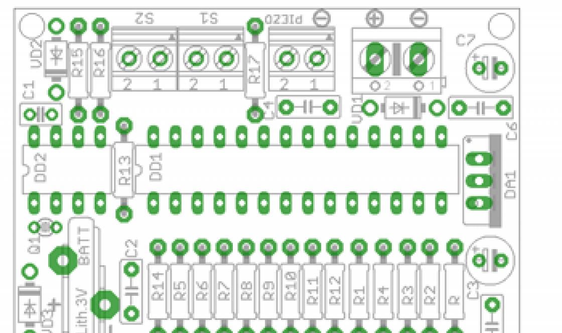
Diagram of a universal measuring device
Meter capabilities
- ESR of electrolytic capacitors - 0-50 Ohm
- Capacity of electrolytic capacitors - 0.33-60,000 μF
- Capacitance of non-electrolytic capacitors - 1 pF - 1 µF
- Inductance - 0.1 µH - 1 H
- Frequency - up to 50 MHz
- Device supply voltage - battery 7-9 V
- Current consumption - 15-25 mA
In ESR mode, it can measure constant resistances of 0.001 - 100 Ohms; measuring the resistance of circuits with inductance or capacitance is impossible, since the measurement is carried out in pulse mode and the measured resistance is shunted. To correctly measure such resistances, you must press the “+” button; in this case, the measurement is carried out at DC 10mA. In this mode, the range of measured resistances is 0.001 - 20 Ohms.

In frequency meter mode, when the “Lx/Cx_Px” button is pressed, the “pulse counter” function is activated (continuous counting of pulses arriving at the “Fx” input). The counter is reset using the “+” button. There is a low battery indication. Automatic shutdown- about 4 minutes. After an idle time of ~ 4 minutes, the inscription “StBy” lights up and within 10 seconds, you can press the “+” button and work will continue in the same mode.

How to use the device
- Turning on/off - briefly pressing the “on/off” buttons.
- Switching modes - “ESR/C_R” - “Lx/Cx” - “Fx/Px” - with the “SET” button.
- After switching on, the device switches to ESR/C measurement mode. In this mode, simultaneous measurement of ESR and the capacitance of electrolytic capacitors or constant resistances of 0 - 100 Ohms is performed. When the “+” button is pressed, resistance measurement is 0.001 - 20 Ohms, measurement is carried out at a constant current of 10 mA.
- Zero setting is necessary every time you replace probes or when measuring using an adapter. Zero setting is done automatically by pressing the corresponding buttons. To do this, close the probes, press and hold the “-” button. The display will show the ADC value without processing. If the values on the display differ by more than +/-1, press the “SET” button and the correct value “EE>xxx” will be recorded<”.
- For the constant resistance measurement mode, zero setting is also required. To do this, close the probes, press and hold the “+” and “-” buttons. If the values on the display differ by more than +/-1, press the “SET” button and the correct value “EE>xxx” will be recorded<”.
Probe design

A metal tulip-type plug is used as a probe. A needle is soldered to the central pin. The side seal is a cover from a disposable syringe. From the available material, a brass rod with a diameter of 3 mm can be used to make a needle. After some time, the needle oxidizes and to restore reliable contact, it is enough to wipe the tip with fine sandpaper.
Device details
- LCD indicator based on the HD44780 controller, 2 lines of 16 characters or 2 lines of 8 characters.
- Transistor PMBS3904 - any N-P-N, similar in parameters.
- Transistors BC807 - any P-N-P, similar in parameters.
- Field effect transistor P45N02 - suitable for almost any computer motherboard.
- Resistors in the circuits of current stabilizers and DA1 - R1, R3, R6, R7, R13, R14, R15, must be the same as indicated in the diagram, the rest can be close in value.
- In most cases, resistors R22, R23 are not needed, while pin “3” of the indicator should be connected to the case - this will correspond to the maximum contrast of the indicator.
- Circuit L101 - must be adjustable, inductance 100 μH at the middle position of the core.
- S101 - 430-650 pF with low TKE, K31-11-2-G - can be found in the KOS of domestic 4-5 generation TVs (KVP circuit).
- C102, C104 4-10 uF SMD - can be found in any old computer motherboard.
- Pentium-3 near the processor, as well as in the boxed Pentium-2 processor.
- DD101 chip - 74HC132, 74HCT132, 74AC132 - they are also used in some motherboards.
Discuss the article UNIVERSAL MEASURING DEVICE
As is well known, not a single amateur radio laboratory can do without means of measuring and monitoring the processes occurring in an electronic device. The modern market offers us entire lines of measuring instruments, from the simplest to the most professional, but not everyone, even the most experienced DIYer, will allow their laboratory to have a full range of available equipment. All this is a consequence of high prices for devices, due to the realities of the modern market. But radio amateurs, as always, find a way out of the situation - they independently design and manufacture measuring equipment for their needs. I invite you to familiarize yourself with the experience of repeating one of these devices, designed by Andrei Vladimirovich Ostapchuk (Andrew).
The universal measuring complex AVO-2006 contains a minimum number of non-scarce and inexpensive parts, and taking into account the functionality of the device, I would venture to call it the simplest that I have ever encountered in my practice! So, what functions does the device have?
Availability of resistance measurement function in the range from 0 to 200,000,000 ohm;
Availability of a function for measuring the capacitance of capacitors in the range from 0.00001 to 2000 μF;
The presence of a single-beam oscilloscope function that allows you to visualize the signal shape, measure its amplitude value and voltage;
Availability of a frequency signal generator function in the range from 0 to 100,000 Hz with the ability to step-by-step change the frequency in steps of 0-100 Hz and display the frequency and duration values on the display;
The presence of a frequency measurement function in the range from 0.1 to 15,000,000 Hz with the ability to change the measurement time and display the frequency and duration values on the display.

If you are impressed by the list of functions supported by the device, I suggest moving on to the recommendations for its manufacture. First of all, a few notes on the components of the device. The most expensive and important part is an LCD indicator with 2 lines of 16 characters each, with a built-in HD44780 controller or its equivalent. The most common are indicators from Winstar and MELT (although my personal preference is Winstar with Russian and Latin fonts). Capacitor C5 should be selected as thermally stable as possible, a film capacitor - the accuracy of measurements of resistance parameters will depend on the invariability of its parameters.

Another important part is the protective zener diode VD1. I’ll make a reservation right away - the use of domestic KS156 zener diodes is impossible, since they have low reverse resistance, and the performance of the device depends on it - the higher the reverse resistance of the zener diode, the better. Imported zener diodes marked on the housing 5V6 or 5V1 are ideal for these purposes. The Atmega8A-PU microcontrollers (analogue of the old Atmega8-16PI and Atmega8-16PU) are ideal for the manufacture of the device, but since today there are many Chinese analogues of these controllers, and with old markings, failures in the operation of the device are not excluded - here we tell you Unfortunately, we cannot help.

Before starting to manufacture the device, I advise you to take a closer look at the LCD indicator. It is better to download the datasheet from the manufacturer’s website (Winstar-www.winstar.com.tw or MELT-www.melt.com.ru). Next, strictly following the datasheet, we connect the screen to the device’s power supply (this can be a simple transformer power supply with an LM317 stabilizer (K142EN5A)

or a 6-volt gel (or any other small-sized and lightweight) battery with the same stabilizer (if someone needs to make a meter for field work). We apply +5 volt voltage to pin 2 of the indicator (see the datasheet - the power pins may change!), and apply the minus to pins 1 and 5. We connect pin 3 of the indicator through a 10 kOhm trimming resistor to the minus of the power supply. By rotating the resistor, we achieve a clear and contrasting display of the entire top line of the indicator. We remove the resistor, measure its resistance and select the same constant - so we have selected resistor R4 for our circuit. We carry out a similar procedure when connecting the display backlight - having achieved optimal brightness, we select a constant resistor - this will be resistor R5 of our circuit. Another important procedure is flashing the microcontroller firmware. Download the HEX file from the author’s website and stitch it into our controller using , not forgetting about the fuse bits of the controller.

You can assemble the device on a breadboard, its wiring is so simple. After the first launch of the device, we begin to calibrate it. To do this, in the resistance measurement mode, when calibrating to zero, we close the measuring probes (crocodiles) with each other, press and hold button 1 and simultaneously press button 2 (save it into memory - OK appears on the screen).


Next, we perform calibration at a nominal value of 1000 Ohm - we attach a precision resistor, press and hold button 2 and simultaneously press button 1 (save it into memory). The device modes are switched in a ring using button 3. To calibrate the device in the capacitance measurement mode, perform the following steps. When calibrating to 0, open the meter probes and press and hold button 1 and write to memory with button 2. When calibrating to 1000pF, hang a precision capacitor, press and hold button 2 and write to memory with button 1. That’s it, the device is ready for use . In other modes, no calibrations are performed.

You can check the operation of the oscilloscope and frequency counter by connecting the device to some kind of working circuit, the measurement results from which were taken in advance using another oscilloscope and frequency counter. You can check the operation of the frequency generator by simply connecting a regular speaker to the output of the device and smoothly changing the frequency using the adjustment keys (1 and 2). The same keys are used to change the sweep time in oscilloscope mode. Changing the frequency measurement time (in frequency meter mode) is carried out by button 1, which allows you to measure frequency with an accuracy of 0.1 Hz.

One small note - make measurements, calibrations and adjustments only with ready-made shielded probes (and not with pieces of mounting wire) - practice shows that different types of cable can introduce significant distortions into the measurement results.

Precision K71-7 are excellent as calibration capacitors, and S2-33N are excellent as calibration resistors.

All parts with a deviation from the nominal value of no more than 1 percent. If, as a result of initial control measurements, it turns out that the linearity of capacitance measurements is too low, we change the resistance of resistor R3 in the range of 50-220 kOhm (the higher the value of this resistor, the higher the accuracy of measurements of small capacitances will be, but accordingly the time for measuring large capacitances will increase significantly); if the linearity of resistance measurement is low, then you will have to select the capacitance of capacitor C5 (of course, you can only change it to one that is equally thermally stable).

Here is a brief summary of all the recommendations for assembling and setting up the device. I gave my device for testing to a friend who works in the instrumentation shop of a local enterprise, and for comparison I also gave him a Chinese measuring device XC4070L (LCR meter). So - according to the results of control measurements made on the enterprise's precision equipment, the AVO-2006 device surpassed the Chinese meter in the accuracy of measuring capacitances and resistances! So draw your own conclusions and stay tuned for further publications in this area.
VII city scientific and practical conference “Step into the future”
Measurement history and simple DIY measuring instruments
Completed: Evgeniy Antakov, student of MBOU Secondary School No. 4,
Scientific supervisor: Osiik T.I. primary school teacher MBOU Secondary School No. 4, Polyarnye Zori

My name is Antakov Zhenya, I 9 years.
I'm in third grade, I do swimming, judo and English.
I want to become an inventor when I grow up.

Project goal: - study the history of measurements of time, mass, temperature and humidity and simulate the simplest measuring instruments from scrap materials.
Hypothesis : I suggested that the simplest measuring instruments can be modeled independently from available materials.
Project objectives :
- study the history of measurements of various quantities;
Familiarize yourself with the design of measuring instruments;
Model some measuring instruments;
Determine the possibility of practical use of homemade measuring instruments.

Scientific article
1. Measuring length and mass
People have been faced with the need to determine distances, lengths of objects, time, areas, volumes and other quantities since ancient times.
Our ancestors used their own height, arm length, palm length, and foot length as means of measuring length.
To determine long distances, a variety of methods were used (arrow flight range, “tubes,” beeches, etc.)
Such methods are not very convenient: the results of such measurements always vary, since they depend on the size of the body, the strength of the shooter, vigilance, etc.
Therefore, strict units of measurement, standards of mass and length gradually began to appear.
One of the oldest measuring instruments is scales. Historians believe that the first scales appeared more than 6 thousand years ago.
The simplest model of scales - in the form of an equal-arm beam with suspended cups - was widely used in Ancient Babylon and Egypt.

Organization of the study
- Rocker scales from a hanger
In my work, I decided to try to assemble a simple model of cup scales, with which you can weigh small objects, products, etc.
I took an ordinary hanger, secured it on a stand, and tied plastic cups to the hangers. The vertical line indicated the equilibrium position.
To determine mass, you need weights. I decided to use regular coins instead. Such “weights” are always at hand, and it is enough to determine their weight once in order to use it for weighing on my scales.
5 rub
50 kopecks
10 rub
1 rub

Organization of the study
Experiments with rocker scales
1. Scale scale
Using different coins, I made marks on a piece of paper corresponding to the weight of the coins
2. Weighing
Handful of candy - balanced using 11 different coins, total weight 47 grams
Check weighing – 48 grams
Cookies - balanced with 10 coins weighing 30 grams On control scales - 31 grams
Conclusion: from simple objects I assembled scales with which you can weigh with an accuracy of 1-2 grams

Scientific article
2.Measurement time
In ancient times, people felt the passage of time according to
the change of day and night and seasons and tried to measure it.
The very first devices for telling time were sundials.
In ancient China, to determine time intervals, a “clock” was used, which consisted of an oil-soaked cord on which knots were tied at regular intervals.
When the flame reached the next node, it meant that a certain period of time had passed.
Candle clocks and oil lamps with marks operated on the same principle.
Later, people came up with the simplest devices - hourglasses and water clocks. Water, oil or sand flows evenly from vessel to vessel, this property allows you to measure certain periods of time.
With the development of mechanics in the 14th and 15th centuries, clocks with a winding mechanism and a pendulum appeared.

Organization of the study
- Water clock made from plastic bottles
For this experiment, I used two 0.5 liter plastic bottles and cocktail straws.
I connected the lids together using double-sided tape and made two holes into which I inserted the tubes.
I poured colored water into one of the bottles and screwed on the caps.
If the entire structure is turned over, the liquid flows down through one of the tubes, and the second tube is necessary for air to rise into the upper bottle

Organization of the study
Experiments with water clocks
The bottle is filled with colored water
Bottle filled with vegetable oil
Liquid flow time – 30 seconds Water flows quickly and evenly
Liquid flow time – 7 min 17 sec
The amount of oil is selected so that the liquid flow time is no more than 5 minutes
A scale was applied to the bottles - marks every 30 seconds
The less oil there is in the top bottle, the slower it flows down, and the distances between the marks become smaller.
Conclusion: I got a watch that can be used to determine time intervals from 30 seconds to 5 minutes

Scientific article
3. Temperature measurement
A person can distinguish between heat and cold, but does not know the exact temperature.
The first thermometer was invented by the Italian Galileo Galilei: a glass tube is filled with more or less water depending on how much the hot air expands or the cold air contracts.
Later, divisions, that is, a scale, were applied to the tube.
The first mercury thermometer was proposed by Fahrenheit in 1714; he considered the freezing point of the saline solution to be the lowest point
The familiar scale was proposed by the Swedish scientist Andres Celsius.
The lower point (0 degrees) is the melting temperature of ice, and the boiling point of water is 100 degrees.

Organization of the study
- Water thermometer
The thermometer can be assembled using a simple scheme from several elements - a flask (bottle) with colored liquid, a tube, a sheet of paper for a scale
I used a small plastic bottle, filled it with tinted water, inserted a juice straw, and secured everything with a glue gun.
While pouring the solution, I ensured that a small part of it fell into the tube. By observing the height of the resulting liquid column, one can judge the temperature changes.
In the second case, I replaced the plastic bottle with a glass ampoule and assembled the thermometer using the same scheme. I tested both devices under different conditions.

Organization of the study
Experiments with water thermometers
Thermometer 1 (with plastic bottle)
The thermometer was placed in hot water - the liquid column dropped down
The thermometer was placed in ice water - a column of liquid rose up
Thermometer 2 (with glass bulb)
The thermometer was placed in the refrigerator.
The column of liquid has dropped down, the mark on a regular thermometer is 5 degrees
The thermometer was placed on the heating radiator
The column of liquid has risen upward, on a regular thermometer the mark is 40 degrees
Conclusion: I received a thermometer that can be used to roughly estimate the ambient temperature. Its accuracy can be improved by using a glass tube with the smallest possible diameter; fill the flask with liquid so that there are no air bubbles left; use an alcohol solution instead of water.

Scientific article
4. Humidity measurement
An important parameter of the world around us is humidity, since the human body reacts very actively to its changes. For example, when the air is very dry, sweating increases and a person loses a lot of fluid, which can lead to dehydration.
It is also known that in order to avoid respiratory diseases, the air humidity in the room should be at least 50-60 percent.
The amount of humidity is important not only for humans and other living organisms, but also for the flow of technical processes. For example, excess humidity can affect the correct operation of most electrical appliances.
To measure humidity, special instruments are used - psychrometers, hygrometers, probes and various devices.

Organization of the study
Psychrometer
One way to determine humidity is based on the difference between the readings of a “dry” and “wet” thermometer. The first shows the temperature of the surrounding air, and the second shows the temperature of the damp cloth with which it is wrapped. Using these readings using special psychrometric tables, the humidity value can be determined.
I made a small hole in a plastic shampoo bottle, inserted a string into it, and poured water into the bottom.
One end of the lace was secured to the flask of the right thermometer, the other was placed in a bottle so that it was in water.

Organization of the study
Experiments with a psychrometer
I tested my psychrometer by determining humidity in various conditions
Near the heating radiator
Near a running humidifier
Dry bulb 23 º WITH
Wet bulb 20 º WITH
Humidity 76%
Dry bulb 25 º WITH
Wet bulb 19 º WITH
Humidity 50%
Conclusion: I found out that a psychrometer assembled at home can be used to assess indoor humidity

Conclusion
The science of measurements is very interesting and diverse; its history begins in ancient times. There are a huge number of different measurement methods and instruments.
My hypothesis was confirmed - at home you can simulate simple instruments (yoke scales, water clock, thermometer, psychrometer) that allow you to determine weight, temperature, humidity and specified periods of time.

Homemade instruments can be used in everyday life if you don’t have standard measuring instruments at hand:
Time yourself doing abdominal exercises, push-ups, or jumping rope
Keep track of time when brushing your teeth
In class, conduct five-minute independent work.

References.
1. “Meet, these are... inventions”; Encyclopedia for children; publishing house "Makhaon", Moscow, 2013
2. “Why and why. Time"; Encyclopedia; publishing house "World of Books", Moscow 2010
3. “Why and why. Inventions"; Encyclopedia; publishing house "World of Books", Moscow 2010
4. “Why and why. Mechanics; Encyclopedia; publishing house "World of Books", Moscow 2010
5. “Big Book of Knowledge” Encyclopedia for children; publishing house "Makhaon", Moscow, 2013
6. Internet site “Entertaining-physics.rf” http://afizika.ru/
7. Website “Watches and Watchmaking” http://inhoras.com/

A huge selection of diagrams, manuals, instructions and other documentation for various types of factory-made measuring equipment: multimeters, oscilloscopes, spectrum analyzers, attenuators, generators, R-L-C, frequency response, nonlinear distortion, resistance meters, frequency meters, calibrators and much other measuring equipment.

During operation, electrochemical processes constantly occur inside oxide capacitors, destroying the junction of the terminal with the plates. And because of this, a transition resistance appears, sometimes reaching tens of ohms. Charge and discharge currents cause heating of this place, which further accelerates the destruction process. Another common cause of failure of electrolytic capacitors is “drying out” of the electrolyte. In order to be able to reject such capacitors, we suggest that radio amateurs assemble this simple circuit
Identification and testing of zener diodes turns out to be somewhat more difficult than testing diodes, since this requires a voltage source exceeding the stabilization voltage.
With this homemade attachment, you can simultaneously observe eight low-frequency or pulse processes on the screen of a single-beam oscilloscope. The maximum frequency of input signals should not exceed 1 MHz. The amplitude of the signals should not differ much, at least there should not be more than a 3-5-fold difference.
The device is designed to test almost all domestic digital integrated circuits. They can check microcircuits of the K155, K158, K131, K133, K531, K533, K555, KR1531, KR1533, K176, K511, K561, K1109 and many others series microcircuits
In addition to measuring capacitance, this attachment can be used to measure Ustab for zener diodes and test semiconductor devices, transistors, and diodes. In addition, you can check high-voltage capacitors for leakage currents, which helped me a lot when setting up a power inverter for one medical device
This frequency meter attachment is used to evaluate and measure inductance in the range from 0.2 µH to 4 H. And if you exclude capacitor C1 from the circuit, then when you connect a coil with a capacitor to the input of the console, the output will have a resonant frequency. In addition, due to the low voltage on the circuit, it is possible to evaluate the inductance of the coil directly in the circuit, without dismantling, I think many repairmen will appreciate this opportunity.
There are many different digital thermometer circuits on the Internet, but we chose those that are distinguished by their simplicity, small number of radio elements and reliability, and you shouldn’t be afraid that it is assembled on a microcontroller, because it is very easy to program.
One of the homemade temperature indicator circuits with an LED indicator on the LM35 sensor can be used to visually indicate positive temperature values inside the refrigerator and car engine, as well as water in an aquarium or swimming pool, etc. The indication is made on ten ordinary LEDs connected to a specialized LM3914 microcircuit, which is used to turn on indicators with a linear scale, and all internal resistances of its divider have the same values
If you are faced with the question of how to measure the engine speed of a washing machine. We'll give you a simple answer. Of course, you can assemble a simple strobe, but there is also a more competent idea, for example using a Hall sensor
Two very simple clock circuits on a PIC and AVR microcontroller. The basis of the first circuit is the AVR Attiny2313 microcontroller, and the second is PIC16F628A
So, today I want to look at another project on microcontrollers, but also very useful in the daily work of a radio amateur. This is a digital voltmeter on a microcontroller. Its circuit was borrowed from a radio magazine for 2010 and can easily be converted into an ammeter.
This design describes a simple voltmeter with an indicator on twelve LEDs. This measuring device allows you to display the measured voltage in the range of values from 0 to 12 volts in 1 volt increments, and the measurement error is very low.
We consider a circuit for measuring the inductance of coils and the capacitance of capacitors, made with only five transistors and, despite its simplicity and accessibility, allows one to determine the capacitance and inductance of the coils with acceptable accuracy over a wide range. There are four sub-ranges for capacitors and as many as five sub-ranges for coils.

I think most people understand that the sound of a system is largely determined by the different signal levels in its individual sections. By monitoring these places, we can evaluate the dynamics of the operation of various functional units of the system: obtain indirect data on the gain, introduced distortions, etc. In addition, the resulting signal simply cannot always be heard, which is why various types of level indicators are used.
In electronic structures and systems there are faults that occur quite rarely and are very difficult to calculate. The proposed homemade measuring device is used to search for possible contact problems, and also makes it possible to check the condition of cables and individual cores in them.
The basis of this circuit is the AVR ATmega32 microcontroller. LCD display with a resolution of 128 x 64 pixels. The circuit of an oscilloscope on a microcontroller is extremely simple. But there is one significant drawback - this is a fairly low frequency of the measured signal, only 5 kHz.
This attachment will make the life of a radio amateur a lot easier if he needs to wind a homemade inductor coil, or to determine unknown coil parameters in some equipment.
We suggest you repeat the electronic part of the scale circuit on a microcontroller with a strain gauge; the firmware and printed circuit board drawing are included in the amateur radio design.
A homemade measurement tester has the following functionality: frequency measurement in the range from 0.1 to 15,000,000 Hz with the ability to change the measurement time and display the frequency and duration on a digital screen. Availability of a generator option with the ability to adjust the frequency over the entire range from 1-100 Hz and display the results on the display. The presence of an oscilloscope option with the ability to visualize the signal shape and measure its amplitude value. Function for measuring capacitance, resistance, and voltage in oscilloscope mode.
A simple method for measuring current in an electrical circuit is to measure the voltage drop across a resistor connected in series with the load. But when current flows through this resistance, unnecessary power is generated in the form of heat, so it must be selected as small as possible, which significantly enhances the useful signal. It should be added that the circuits discussed below make it possible to perfectly measure not only direct, but also pulsed current, although with some distortion, determined by the bandwidth of the amplifying components.
The device is used to measure temperature and relative humidity. The humidity and temperature sensor DHT-11 was taken as the primary converter. A homemade measuring device can be used in warehouses and residential areas to monitor temperature and humidity, provided that high accuracy of measurement results is not required.
Temperature sensors are mainly used to measure temperature. They have different parameters, costs and forms of execution. But they have one big drawback, which limits the practice of their use in some places with a high ambient temperature of the measurement object with a temperature above +125 degrees Celsius. In these cases, it is much more profitable to use thermocouples.
The turn-to-turn tester circuit and its operation are quite simple and can be assembled even by novice electronics engineers. Thanks to this device, it is possible to test almost any transformers, generators, chokes and inductors with a nominal value from 200 μH to 2 H. The indicator is able to determine not only the integrity of the winding under test, but also perfectly detects inter-turn short circuits, and in addition, it can check p-n junctions of silicon semiconductor diodes.
To measure an electrical quantity such as resistance, a measuring device called an Ohmmeter is used. Devices that measure only one resistance are used quite rarely in amateur radio practice. The majority of people use standard multimeters in resistance measurement mode. Within the framework of this topic, we will consider a simple Ohmmeter circuit from the Radio magazine and an even simpler one on the Arduino board.
DIY Tesla coil. Tesla's resonant transformer is a very impressive invention. Nikola Tesla perfectly understood how spectacular the device was, and constantly demonstrated it in public. Why do you think? That's right: to get additional funding.
You can feel like a great scientist and amaze your friends by making your own mini-reel. You will need: a capacitor, a small light bulb, a wire and a few other simple parts. However, remember that the Tesla resonant transformer produces high voltage, high frequency - read the technical safety rules, otherwise the effect may turn into a defect.
Potato cannon. An air gun that shoots potatoes? Easily! This is not a particularly dangerous project (unless you decide to make a giant and very powerful potato weapon). The potato cannon is a great way to have fun for those who love engineering and mischief. The super weapon is easy to make - you just need an empty aerosol spray bottle and a couple of other spare parts that are easy to find.
High power toy machine gun. Remember children's toy machines - bright, with different functions, bang-bang, oh-oh-oh? The only thing that many of the boys lacked was for them to shoot a little further and a little harder. Well, this can be fixed.
Toy machines are made of rubber to make them as safe as possible. Of course, manufacturers have made sure that the pressure in such pistols is minimal and cannot cause harm to anyone. But some craftsmen have still found a way to add power to children's weapons: you just need to get rid of the parts that slow down the process. From which ones and how - says the experimenter from the video.
Drone with your own hands. Many people think of a drone solely as a large unmanned aerial vehicle used in military operations in the Middle East. This is a misconception: drones are becoming an everyday occurrence, in most cases they are small, and making them at home is not that difficult.
Parts for a “home” drone are easy to obtain, and you don’t have to be an engineer to assemble the whole thing – although, of course, you will have to tinker. The average handmade drone consists of a small main part, a few additional parts (can be purchased or found from other devices) and electronic equipment for remote control. Yes, it’s a special pleasure to equip a finished drone with a camera.
Theremin- music of the magnetic field. This mysterious electro-musical instrument is of interest not only (and not so much?) to musicians, but to mad scientists. You can assemble this unusual device, invented by a Soviet inventor in 1920, at home. Imagine: you simply move your hands (of course, with the languid air of a scientist-musician), and the instrument makes “otherworldly” sounds!
Learning to masterly operate a theremin is not an easy task, but the result is worth it. Sensor, transistor, speaker, resistor, power supply, a couple more parts, and you're good to go! This is what it looks like.
If you don’t feel confident in English, watch a Russian-language video on how to make a theremin from three radios.
Remote controlled robot. Well, who hasn't dreamed of a robot? And even self-assembled! True, a fully autonomous robot will require serious expertise and effort, but a remote-controlled robot can be created from scrap materials. For example, the robot in the video is made of foam, wood, a small motor and a battery. This “pet”, under your guidance, moves freely around the apartment, overcoming even uneven surfaces. With a little creativity, you can give it the look you want.
Plasma ball I've probably already attracted your attention. It turns out that you don’t need to spend money on purchasing it, but you can gain confidence in yourself and do it yourself. Yes, at home it will be small, but still one touch to the surface will cause it to discharge with the most beautiful multi-colored “lightning”.
The main ingredients are an induction coil, an incandescent lamp and a capacitor. Be sure to follow safety precautions - this spectacular device operates under voltage.
Solar powered radio- An excellent device for lovers of long hikes. Don't throw away your old radio: just attach a solar panel to it and you'll be independent of batteries and other power sources other than the sun.
This is what a solar-powered radio looks like.
Segway today it is incredibly popular, but is considered an expensive toy. You can save a lot by spending only a few hundred dollars instead of a thousand, adding your own time and effort, and making a Segway yourself. This is not an easy task, but it is quite possible! Interestingly, today Segways are used not only for entertainment - in the United States they are used by postal workers, golfers and, most strikingly, experienced Steadicam operators.
You can get acquainted with the detailed almost hour-long instructions - however, it is in English.
If you doubt that you have understood everything correctly, below are the instructions in Russian - to get a general idea.
Non-Newtonian fluid allows you to do a lot of fun experiments. It's absolutely safe and exciting. A non-Newtonian fluid is a fluid whose viscosity depends on the nature of the external influence. It can be made by mixing water with starch (one to two). Do you think it's easy? Not so. The “tricks” of a non-Newtonian fluid begin already in the process of its creation. Further - more.
If you take a handful of it, it will look like polyurethane foam. If you start throwing it up, it will move like it’s alive. Relax your hand and it will begin to flow. Squeeze it into a fist and it will become hard. It “dances” if you bring it to powerful speakers, but you can also dance on it if you stir enough for this. In general, it’s better to see it once!