- alarm.
– thermometer.
1. Functions.
– indication. Alternately.
PLUSMINUS
2. Setup.
2.2. By pressing a buttonMENUSET
Group CLOC:
– minutes;
- watch;
PLUS or MINUS);
With".
Group ALAr:
OnOFF" if disabled;
Group diSP:
tc
tt
EF, Ar
P
Group LiGH:
A", in the younger ones" OnOF
L_ ".
L¯ ".
L– ".
2.4. By holding the buttonsPLUS/ MINUS
3. Notes.
topic .
Video of the program working t userwolf2000.
– watch with digital accuracy correction.
- alarm.
– thermometer.
– indication on a seven-segment indicator.
– automatic adjustment of indicator brightness.
1. Functions.
– clock, time display format 24-hour, hours:minutes.
– digital accuracy correction. Daily correction is possible ±25 sec. The set value of 1 hour 0 minutes 30 seconds will be added/subtracted from the current time.
- alarm. IN specified time Short double signals are heard within one minute. You can turn off the sound ahead of schedule by pressing any of the buttons. When the alarm clock is enabled, a dot is displayed in the least significant digit when the time is displayed.
– thermometer. The range of measured temperature is -55.0 ÷ 125.0 o C. If the temperature is above 99.9 or below -9.9 o C, tenths of a degree are not displayed.
– indication. Alternately.
– customizable animation of changing readings.
– use of non-volatile memory of the microcontroller to save settings when the power is turned off.
– if in the main mode you press the buttonPLUS, then the time is displayed on the indicators if you click onMINUS- temperature. When the buttons are released, the automatic change of readings resumes.
– automatic adjustment of the brightness of the indicator depending on the illumination.
2. Setup.
2.1. When the power is turned on, the clock is in main mode.
2.2. By pressing a buttonMENUenters the settings mode and selects a group of parameters to install. Within a group, the parameter to be set is selected using the buttonSET. Available for installation in turn:
Group CLOC:
– minutes;
- watch;
– seconds (reset to zero when you press the buttonsPLUS or MINUS);
– correction value. In the most significant digit the symbol " With".
Group ALAr:
– activation of the alarm clock. On the indicator "On"if the alarm clock is enabled, "OFF" if disabled;
– minutes when the alarm goes off;
– alarm clock time.
Group diSP:
– time of indication of the current time. In the highest digits the symbols "tc". Setting range 0÷99 sec. If set to 0, the time will not be displayed;
– temperature indication time. In the highest digits the symbols "tt". Setting range 0÷99 sec. If set to 0, the temperature will not be displayed;
– selection of animation effect. In the highest digits the symbols "EF". If set to 0, information changes will be carried out without effects, if automatic mode is selected (symbol " A"), then the effects will change one by one. If the mode is selectedr, then the effects will change randomly.
– select animation speed. In the most significant digit the symbol "P". The setting range is 0÷99. One unit corresponds to approximately 2 ms, the higher the value, the slower the animation.
Group LiGH:
– switching on automatic control indicator brightness. In the most significant digit the symbol "A", in the younger ones" On" if automatic regulation is enabled, "OF" if the brightness is set manually;
– minimum brightness threshold for automatic mode. In the highest digits the symbols "L_ ".
– maximum brightness threshold for automatic mode. In the highest digits the symbols "L¯ ".
– brightness level in manual mode. In the highest digits the symbols "L– ".
2.3. The parameter being set flashes.
2.4. By holding the buttonsPLUS/ MINUSthe parameter is quickly set.
3. Notes.
1. For the minimum and maximum brightness thresholds, the setting range is 0 ÷ 99, but the program introduces restrictions: the minimum cannot be greater than or equal to the maximum and vice versa.
2. When setting the brightness parameters, the information on the indicator is displayed with the selected brightness value.
3. It is necessary to compare the speed of animation and the time of displaying information. If slow animation and short display time are selected, it may turn out that the information does not have time to be completely updated before the next shift.
A topic has been created to discuss the materials of the article.
Video of the program working t userwolf2000.
Watch on ATmega8.
- 10 alarms for every day of the week.
- Delay of the signal, if the alarm is not turned off, goes off after about 5 minutes.
- Two alarm clocks on a separate MK leg, load on/off.
- Two DS18B20 temperature sensors (at home and outdoors).
- Selection of temperature display (zero blanking).
- Timer 99 hours.
- The brightness of the indicator is adjustable for daytime and nighttime.
- The variable parameter smoothly changes the brightness.
- When 220 volts are lost, battery consumption is less than 40 microamps.
- The alarm goes off in any power mode.
- The watch can show up to 8 modes.
- The circuit can use indicators with a common anode or cathode.
The watch can show up to 8 modes, for which you can select one of fifteen display formats, the time it will be shown and the number of times it will be skipped.
| Display formats. | ||
| 0 |
Date, Day of the week, Hours-minutes. |
|
|---|---|---|
| 1 |  |
Hours-minutes-seconds. |
| 2 |  |
Hours and minutes. |
| 3 |  |
Hours-minutes, Day of the week. |
| 4 |  |
Day_of_month_day of week. |
| 5 |  |
Date month year. |
| 6 |  |
Day month year day of week. |
| 7 |  |
|
| 8 |  |
Temperature 1 sensor (house sensor). |
| 9 |  |
Temperature 2 sensor (sensor outside). |
| A |  |
Temperature 1 sensor, Hours-minutes. |
| b |  |
Temperature 2 sensor, Hours-minutes. |
| C |  |
Temperature 1 sensor, Temperature 2 sensor. |
| d |  |
Temperature 1 sensor, Temperature 2 sensor. |
| E |  |
Day of the week number month year. |
| F |  |
Date month year. |
|
In modes where tenths of degrees are not indicated, the point determines more than 0.5 degrees. |
||
Button F - exit the mode. Choice of 3 main modes.
SET button - enters the selected mode. Next, move to the next parameter (flashing field).
PLUS button - plus/on. In SETUP mode, scroll through the main menus.
MINUS button - minus/__(off). In SETUP mode, scroll through the main menus.
All modes, except zero and timer modes, have a time termination. If there are no presses for more than 30 seconds, mode is set to zero.
CALLS mode
SETUP mode.
To write values to EEPROM, you need to confirm all values in the submode by pressing SET.
Example: LIGHT ->SET-> L.ooooo ->SET-> НО4ь L.2 ->SET-> LIGHT .
PORT mode.
Clock mode.
| Adjusting seconds. Pressing MINUS resets the seconds to zero. If there were more than 31 seconds, then the minutes are incremented. Next comes setting the minutes and hours. |
|
| Installed: day, month, year and day of the week. |
|
 |
Clock correction. This value is added or subtracted every hour. Step 0.008 seconds. (50 values), maximum value 0.391. Calculation example: with a correction equal to zero, the clock drift is measured, for example, in 5 days the clock has run away by 3 seconds, then the correction is exactly 3/(5*24)=0.025. |
Set SEE mode.
| In zero mode, the clock alternately shows up to 8 modes, for which one of ten display formats and the time of its display is selected (top table). | |
 |
1
mode selection. r 5 select one of fifteen display formats. With 03 time in seconds that the selected mode will be visible. n 0 how many times to skip (do not show) mode. Example: 1 r0 c03n0 2 r5 c03n0 3 r4 c02n1 r0; r5; r4; r0; r5; r4; r0; r5; r4; r0; r5; r4; .. r4; — visible, r4; - missed. When the time is 00, the mode is disabled. |
Mode USt Bud. Alarm settings.
 |
Bip alarm signal - PWM. Pin alarm signal - mouth in 1 output bud. Both Shim and output. |
 |
Signal delay. Sets the number of signal delays. When off Snooze (00) turns off the alarm by pressing any key. When on alarm snooze off button F, when pressing the SET PLUS MINUS buttons, the signal turns off, but will work again after about 5 minutes. When signal delay is active, in zero mode, the dot of the last digit flashes. |
 |
Disable delay (if there is no signal). In mode 0, pressing SET on. this mode. The presence of an active delay induces the symbol O at the 4th acquaintance place. Pressing PLUS MINUS turns off the delay. |
DS18B20 mode.
Light mode.
Signal mode.
Reset mode.
Actions in zero mode.
F - mode selection.
SET - signal delay cancel mode
PLUS - Set SEE mode.
MINUS - setting alarms.
Every hour, for one second, pin PB2(16) is set.
To save money, signal delay is prohibited in battery mode. The timer also stops.
Source WinAVR-20060421. Firmware anode, cathode and firmware for a circuit with large indicators. With automatic transition to summer/winter time.
No changeover to summer/winter time.
Diagram for large indicators. Sent by Alexey.
This article describes the design of digital hours on the Attmega8 microcontroller, which are equipped with a stopwatch, alarm clock, and countdown timer. The watch has a day and date display function with the ability to display the date and time combined. Available automatic switching for summer and winter time, as well as taking into account leap years.
The display is built on six 7-segment LED indicators with brightness adjustment. The watch is also equipped with battery backup.
Description of the microcontroller clock design
As mentioned above, the watch has a six-digit display, consisting of two three-digit T-5631BUY-11 displays, operating in multiplex mode. The indicator anodes are grouped by category and are switched using transistors T1...T6.
The cathodes are grouped into segments and are powered directly from the IO1 Attmega8 microcontroller. The multiplexing frequency is 100Hz.
Clock controlled by low frequency quartz resonator X1 with a frequency of 32768 Hz. By activating the CKOPT bit, which allows the use of internal 36pF capacitors for quartz, there is no need to use external capacitors.

If you have problems starting the generator, you can try connecting 2 22pf capacitors. For even greater clock accuracy, you can completely turn off the internal capacitors (reset the CKOPT bit) and leave only the external ones.
The piezo emitter REP1 emits an alarm sound and signals the end of the timer. During sound signal Logic 1 appears at pin 16 (port PB2). This signal can be used to control any load.
The watch is controlled by three buttons - minutes, hours and mode. The buttons are connected through resistors that protect the ports of the Attmega8 microcontroller. The circuit is powered by a 5 volt source (7805). Current consumption mainly depends on the number of active indicators, as well as on the degree of brightness adjustment.
At maximum brightness, current consumption reaches 60 mA. The watch is equipped with a backup battery. While running on battery power, the watch enters an economy mode in which the display is turned off. Also in this mode, the buttons are not active, except when it is necessary to turn off the sound signal.
The backup voltage is from 3 to 4.5 V. This can be one 3V battery, three 1.2V NiMH or NiCd batteries, or one Li-Pol or Li-Ion battery (3.6 to 3.7V). The current consumption from a 3V battery is only 5...12mA. Time battery life Hours in economy mode from a 3V CR2032 battery with a standard capacity of 200mAh should theoretically last for about 2.5 - 3 years.
The software for the microcontroller is at the end of the article. The configuration bits must be set as follows:

Clock management
The clock is controlled using TL1-minute, hour-TL2 and TL3-mode. The hour and minute buttons are used in clock mode to assign hours and minutes. In other modes they have various functions. The mode button switches between different modes, of which there are 8 in total:
Mode 1 - Clock
In this mode, the display shows the current time in the format “HH.MM.SS”. The clock button is used to set the clock. Minutes button to set the minutes. When pressed, the seconds are reset.
Mode 2 - Enabling daylight saving time and setting the year
Here you can turn on or off the automatic changeover between summer and winter time and set the year. The data is in the following format “AC ‘RR” (AC – automatic time, space, last two digits of the year).
Mode 3 - Countdown timer
This mode allows you to organize a countdown from a given value to zero. After this time has elapsed, a beep will sound and LED1 will light up. The beep can be stopped by pressing the Mode button. The data is in the following format: "HH.MM.SS". Maximum possible meaning is 99.59.59 (almost 100 hours).
Mode 4 – Combined information output
In this mode, the following are displayed alternately:
- current time in the format "HH.MM.SS"
- date in the format “AA.DD.MM.”
Each format is displayed for 1 second. In this mode, the Hour and Minute buttons are used to adjust the brightness of the display (Hours-, Minutes+). The brightness changes logarithmically in 6 steps: 1/1, 1/2, 1/4, 1/8, 1/16 and 1/32nd. Default is 1/2
Mode 5 - Setting the day of the week and alarm mode
In this mode, you can set the day of the week - from Monday to Sunday (displayed as Mon, Tue, Wed, Thu, Fri, Sat, Sun), turn on the alarm and select its operating mode. The data is in the following format "AA AL._" (day of the week, space, AL., alarm setting).
The clock button sets the day of the week. The minute button is used to turn on/off the alarm sound and select its operating mode: “AL._” = alarm is not active, “AL.1” = alarm beeps 1 time (then automatically switches to “AL._” position), “ AL.5" = alarm sounds only on weekdays (Mon-Fri, except Sat-Sun), "AL.7" = alarm rings every day
Mode 6 – Setting the day of the week and date
The clock button allows you to set the day of the month. The minute button allows you to set the month.
Mode 7 - Stopwatch
The stopwatch allows you to measure time with an accuracy of 0.1 seconds. Maximum time measurement is 9.59.59.9 (almost 10 hours). The data is in the following format "H.MM.SS.X". The minute button is used to start and stop the stopwatch. The clock button is used to reset.
Mode 8 - Alarm clock
This mode is used to display and set the alarm time (ALARM). The data is in the following format "HH.MM.AL". The Minutes button sets the alarm minute, the Clock button sets the alarm hour.
Below is a diagram of a similar watch that has an indicator with a common cathode

(downloads: 812)
Electrical circuit diagram

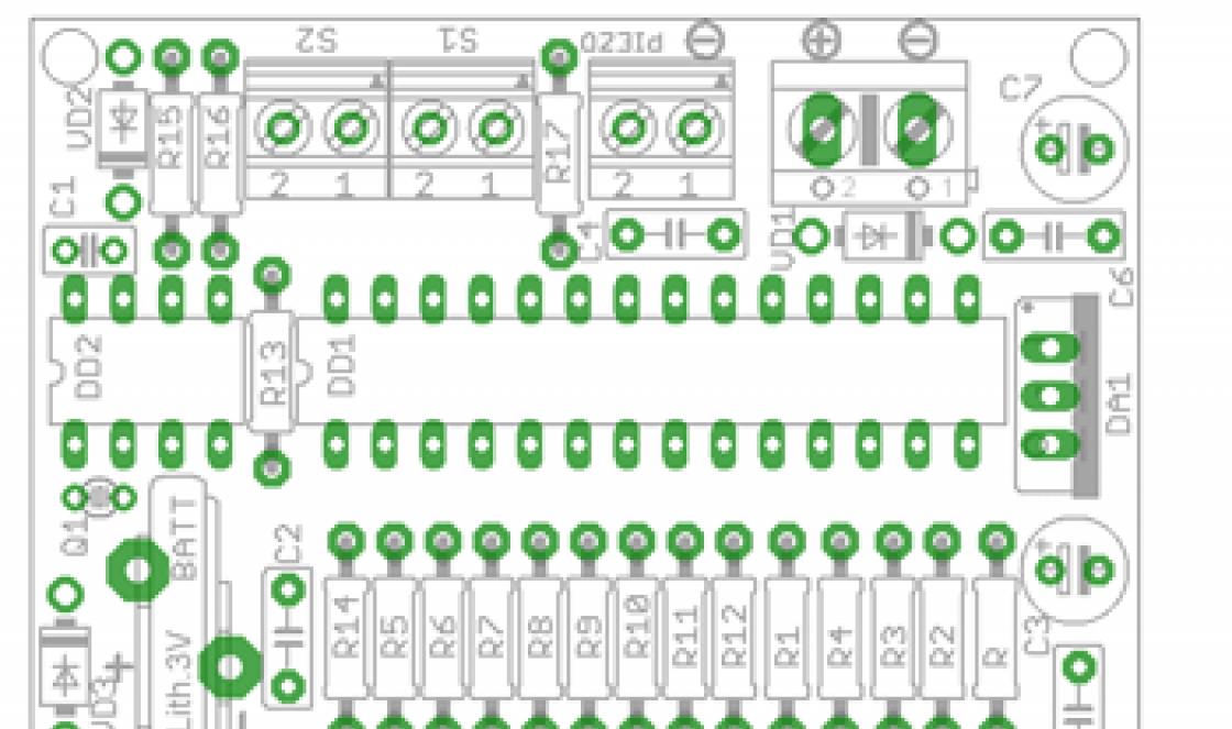
One device combines two functions: the actual measurement of temperature and time (clock). The display is performed alternately, changing every ten seconds. To set the clock, two buttons are used, similar to a simple Chinese electronic clock: one is responsible for selecting a parameter, the second for changing it. The device is powered from the network using a constant stabilized current source of five volts (board from the phone charger).


The temperature sensor is a DS18B20 chip. Since the Clock-Thermometer device does not have its own battery, if the power is lost, the readings will naturally be lost. And so that this does not cause a person to be late for vital matters, there is an interesting “trick” - when power is applied, dashes will be displayed on the display instead of time until you press one of the two setting buttons.


The body of the homemade temperature meter was a suitable cufflink box. The clock-thermometer board itself and the board taken out from the telephone charger were placed in it. The DS18B20 sensor is made remote and connected via a connector.


List of required parts
- Atmega8 microcontroller - 1 pc.
- Quartz 32768 Hz - 1 pc.
- Temperature sensor DS18B20 - 1 pc.
- Seven segment indicator (4 digits) - 1 pc.
- SMD resistors size 0805:
- 620 Ohm - 8 pcs.
- 0 Ohm (jumper) - 1 pc.
- 4.7 kOhm - 1 pc.
- Tact buttons - 2 pcs.
Video of the device on YouTube channel
I bring to your attention a simple diagram and design “ Two-channel thermometer, clock on ATmega8, DS18B20, DS1307, LCD (ZhK) 1602«.
The design allows you to display the current time, date, month, day of the week and current temperature from two digital temperature sensors on a two-line symbol indicator.
Diagram of a two-channel thermometer and clock
The design is assembled on an ATmega8-16PU microcontroller, a DS1307 real-time clock chip in a DIP package, DS18B20 digital temperature sensors, and an LCD1602 LCD indicator

The device diagram was created in the program
Temperature sensors are connected to connectors DS1 and DS2:
— pin 1 — to the GND pin of the sensor
— pin 2 — to the DQ pin of the sensor
— pin 3 — to the Vcc pin of the sensor
The connection of the sensors in the diagram does not correspond printed circuit board.
The program is tailored to the printed circuit board, you need to connect:
— 1st sensor to PB1 (15th pin)
— 2nd sensor to PB2 (16th pin)
I draw your attention to connecting the pins of port D of the microcontroller to the pins of the indicator:
- PD0 of the microcontroller - to pin D7 of the indicator
- PD1 of the microcontroller - to pin D6 of the indicator
- PD2 of the microcontroller - to pin D5 of the indicator
- PD3 of the microcontroller - to pin D4 of the indicator
This connection was chosen to simplify the layout of tracks on the printed circuit board.
Details used in the design:

The LCD display is 2-line, 16-character negative, white characters on a dark blue background with white backlighting. You can also use any similar character-synthesizing (symbolic) two-line, 16-character indicator, with or without Cyrillic support, that supports the command system of the HD44780 type controller:
— STN (FSTN) Negative (blue or black) with backlight (this is used in the design) — such indicators only work with backlight
— FSTN Positive, TN Positive, HTN Positive — with or without backlight
The Chinese LCD indicator used does not have a built-in Cyrillic alphabet, therefore, for clarity of displaying the day of the week on the indicator, custom characters are written into the character generator RAM (CGRAM) - “P”, “n”, “t”, “Ch”, “b” and two characters in inverse form “D” and “U”.
Printed circuit board of a two-channel thermometer and clock
The design is assembled on a single-sided printed circuit board, all used parts are “output”
The device's printed circuit board was created in the program.
There are three jumpers on the board - P1, P2, P3
The quartz resonator is installed “lying” on the board; the resonator body is soldered with a jumper to the contact pad on the board under the resonator.

Description of the operation of a two-channel thermometer and clock
The basis of the design "D" two-channel thermometer, clock" is a microcontroller ATmega8 in DIP package with clock frequency 1 MHz from built-in oscillator with internal RC circuit. Setting FUSE bits is the default, no need to change anything.
A real-time clock chip is used to determine the current time DS1307, which counts seconds, minutes, hours, date of month, month, day of week and year with leap year compensation valid until 2100.
Only the following are displayed:
- current time - hours and minutes
- date of month
- month
- day of the week
Two digital temperature sensors are used as temperature sensors DS18В20, which allow you to measure the current temperature ranging from -45 degrees to +125 degrees Celsius with an accuracy of 0.5 degrees.
The current temperature of each sensor is displayed with a resolution of 0.1 °C
Before the value of each temperature, the symbols “D” and “U” are displayed in inverse form:
- “D” - temperature in the house
— “U” — outside temperature

The program's operation is organized by overflow interrupts from timer T1 occurring every 4 seconds. The current time is updated every 4 seconds, the current temperatures from the sensors are updated alternately, every 4 seconds.
The device is powered from a stabilized 5 Volt power source, you can use charger from cell phone, or an autonomous power source - battery. The current consumption depends on the brightness of the backlight (the value of resistor R3) and in a particular case is 12 mA.
The device is controlled by two buttons:
— S1 — “Selection”
— S2 — “Installation”
When the device is turned on for the first time (or every time it is turned on in the absence of a backup power supply DS1307 - BAT1), the device goes into the “Full” installation mode. In this case, it is necessary to set the current year, month, date, day of the week and current time - hours and minutes. In this mode, the explanatory information was not translated into Russian (unlike the day of the week indication), all explanations are displayed in English (a complete installation is performed extremely rarely, it is not difficult to understand):
Setting the Year:
A blinking cursor in the form of a white rectangle indicates where and what needs to be entered:
— with the “Install” button — we set it to tens of years
- using the “Select” button - proceed to setting the year units
— using the “Setup” button — set the value of the year units
— with the “Select” button — go to the next setting
 Setting the month to “Month”
- similar to setting the year
 Setting the day of the month “Data”:
- similar to setting the year
 Setting the day of the week “Week”:
- similar to setting the year, with - 1 - Mon, 2 - Tue, 3 - Wed, 4 - Thu, 5 - Fri, 6 - Sat, 7 - Sun
 Setting the current time “Hour_Min”
For example, the current time is 17 hours 39 minutes:
— with the “Install” button — we set tens of hours — 1
— using the “Select” button — proceed to setting the hour units
— using the “Setup” button — set the hour units — 7
— using the “Select” button — go to setting tens of minutes — 4
— using the “Setup” button — set the minutes units to -0
— the seconds are already indicated on the displays as “00”
— at exactly 17 hours 40 minutes press the “Select” button and the current time 17 hours 40 minutes 00 seconds will be recorded in DS1307

In operating mode, the “Select” and “Install” buttons allow you to switch to the following modes:
— Select button— time correction (in this case, only the current time “Hour_Min” is set as described above)
— "Install" button— “Full” installation
To login desired mode you must press the corresponding button and hold it until the display screen clears. After clearing the display, release the button and after a second we go to the selected mode.
The design was developed and tested on a breadboard; it was not assembled in hardware.
There were many comments about the device not working and the printed circuit board not matching the circuit diagram.
It was decided to recreate the device in hardware.
Below are photographs of the assembled device according to the circuit, printed circuit board and firmware published on this page.
The device started working immediately, no problems observed.
The printed circuit board is made using the LUT method. Due to an error in installing the microcircuits on the board, they had to be desoldered and rearranged (and there is a hole in the old woman), which led to damage to the printed circuit conductors and, as a result, - appearance not very good, jumper P2 is installed on the side of the printed circuit conductors (did not drill holes), sensor DS1 is connected with a cable about 1 meter long (so that it is at a height of about 30 cm from the floor, sensor DS2 is connected with a cable 5 meters long and placed outside the window. The connectors for connecting sensors were taken from coolers of old computers.
There was one problem - the RTC DS1307 did not start right away, the reason was rosin between the quartz pins. After washing the board, the clock started working.


(10.8 KiB, 1,995 hits)
(27.3 KiB, 1,473 hits)
(390.1 KiB, 1,296 hits)
(51.7 KiB, 2,494 hits)
Download from YandexDisk (additionally - datasheets in Russian)
You can order all the necessary parts for assembling a “Dual-channel thermometer, clock on ATmega8, DS18B20, Ds1307”, including a programmed microcontroller at online store site