Seal
Power supply repair
Among all faults, repair of power supplies ranks first. In the article “TV power supply malfunctions” I described typical malfunctions of power supplies. In this article I want to describe the operation and repair of power supplies in more detail.
You probably need to start with how to check after power supply repair so as not to cause it to break again. Although this method is considered controversial, I find it very effective.
So after power supply repair you need to solder a 150-watt light bulb into the fuse gap (100-watt is possible, but there may be a false glow), and solder a 40-60-watt light bulb into the B+ circuit gap (the horizontal scan power is 95-145 volts, the track can simply be cut). Please note that some power supplies do not start with a small load.
This is how this system works. When connected to the network after repairing the power supply, if it is in good working order, the first light bulb lights up at the moment of charging the mains capacitor (100-220 μF 450V) and goes out as it charges. A weak glow remains. A 60 W light bulb glows according to the voltage at half incandescent.
If the power supply is faulty, a 150 W light bulb glows at full intensity. In some cases, this saves a transistor or a microcircuit from repeated failure of key elements.
In the second method, the power transistor of the power supply is not soldered in and the level and shape of the signal arriving at it are analyzed using instruments (oscilloscope, multimeter).
Power supply repair.
In the description I will rely on the diagram below.

When the power is turned on, the mains fuse blows.
Malfunctions may be caused by:
- demagnetization system;
- surge protector and rectifier;
- key malfunction.
We check for short circuits the elements of the network filter, rectifier, thermistor - demagnetization system, the key and its wiring elements, as well as the key microcircuit (if the power supply is built on it).
If you find a faulty element, analyze the reasons for its failure. Failure of a transistor can be caused either by a voltage surge in the network or by drying out of capacitors in the primary circuits.
The power supply does not turn on, the mains fuse is intact.
You should check for a break: line filter, rectifier, PWM modulator.
Start by checking if there is a constant voltage of about 300V across the mains capacitor C (if not, you should look for an open circuit in the mains filter, and also check the resistor R.
If there is +300V on capacitor C, check whether it reaches the key transistor. You should also check the primary winding of the mains pulse transformer TP for a break.
If all elements are in good working order, but the power supply does not turn on, you need to check the flow of pulses to the base (gate) of the transistor.
Also check the start circuit R, usually these are high resistance resistors.
Power supply protection is triggered.
Check: elements of the secondary rectifiers of the power supply, power supply loads for short circuits, elements of the protection system (output voltage monitoring circuits), feedback circuits (modulator).
I think everything is clear with the secondary circuits and their loads; it is necessary to check the rectifiers (diodes) and filter capacitors.
In the protection circuits, check the optocoupler and its wiring.
Regarding the feedback circuits, check the zener diodes, diodes, capacitors (usually 4.7-10-47 uF).
Voltages are too high or too low.
Check:
Mains capacitor, PWM binding capacitors, serviceability of the optocoupler and its wiring.
Malfunctions appear periodically.
In this case, you should proceed as follows:
- check the soldering of the power supply elements for ring cracks;
- check the elements in the places of greatest heating on the board, identifying them by blackening.
- If a malfunction occurs when the TV is warming up, you can localize the faulty element either by cooling (cotton wool moistened with acetone or alcohol), or to speed up the appearance of the malfunction, provoke it by heating one or another element with a soldering iron.
They have always been important elements of any electronic devices. These devices are used in amplifiers and receivers. The main function of power supplies is considered to be to reduce the maximum voltage that comes from the network. The first models appeared only after the AC coil was invented.
Additionally, the development of power supplies was influenced by the introduction of transformers into the device circuit. The peculiarity of pulse models is that they use rectifiers. Thus, voltage stabilization in the network is carried out in a slightly different way than in conventional devices where a converter is used.
Power supply device
If we consider a conventional power supply, which is used in radio receivers, then it consists of a frequency transformer, a transistor, and several diodes. Additionally, the circuit contains a choke. Capacitors are installed with different capacities and their parameters can vary greatly. Rectifiers are usually used of the capacitor type. They belong to the high-voltage category.
Operation of modern blocks
Initially, the voltage is supplied to the bridge rectifier. At this stage, the peak current limiter is activated. This is necessary so that the fuse in the power supply does not burn out. Next, the current passes through the circuit through special filters, where it is converted. Several capacitors are needed to charge the resistors. The unit starts up only after a breakdown of the dinistor. Then the transistor is unlocked in the power supply. This makes it possible to significantly reduce self-oscillations.
When voltage generation occurs, the diodes in the circuit are activated. They are connected to each other using cathodes. A negative potential in the system makes it possible to lock the dinistor. The rectifier start-up is facilitated after the transistor is turned off. In addition, two fuses are provided to prevent saturation of the transistors. They operate in the circuit only after a breakdown. To start feedback, a transformer is required. It is fed by pulsed diodes in the power supply. At the output, alternating current passes through capacitors.

Features of laboratory blocks
Operating principle of switching power supplies of this type built on active current conversion. There is one bridge rectifier in the standard circuit. In order to remove all interference, filters are used at the beginning and also at the end of the circuit. The pulsed laboratory power supply has conventional capacitors. Saturation of transistors occurs gradually, and this has a positive effect on diodes. Voltage regulation is provided in many models. The protection system is designed to save blocks from short circuits. Cables for them are usually used in a non-modular series. In this case, the power of the model can reach up to 500 W.
The power supply connectors in the system are most often installed as ATX 20 type. To cool the unit, a fan is mounted in the case. The speed of rotation of the blades must be adjusted in this case. A laboratory-type unit should be able to withstand the maximum load at 23 A. At the same time, the resistance parameter is maintained on average at 3 ohms. The maximum frequency that a switching laboratory power supply has is 5 Hz.

How to repair devices?
Most often, power supplies suffer due to blown fuses. They are located next to the capacitors. Repair of switching power supplies should begin by removing the protective cover. Next, it is important to inspect the integrity of the microcircuit. If no defects are visible on it, it can be checked using a tester. To remove fuses, you must first disconnect the capacitors. After this they can be removed without any problems.
To check integrity of this device inspect its base. Burnt fuses have a dark spot at the bottom, which indicates damage to the module. To replace this element, you need to pay attention to its markings. Then you can purchase a similar product in a radio electronics store. Installation of the fuse is carried out only after fixing the condensates. Another common problem in power supplies is considered to be faults with transformers. They are boxes in which coils are installed.
When very high voltage is applied to the device, they cannot withstand it. As a result, the integrity of the winding is compromised. It is impossible to repair switching power supplies with such a breakdown. In this case, the transformer, like the fuse, can only be replaced.
Network power supplies
The operating principle of network-type switching power supplies is based on a low-frequency reduction in the amplitude of interference. This happens thanks to the use of high-voltage diodes. Thus, it is more effective to control the limiting frequency. Additionally, it should be noted that transistors are used at medium power. The load on the fuses is minimal.
Resistors are used quite rarely in a standard circuit. This is largely due to the fact that the capacitor is capable of participating in current conversion. The main problem with this type of power supply is the electromagnetic field. If capacitors are used with low capacitance, then the transformer is at risk. In this case, you should be very careful about the power of the device. Limiters for network peak current pulse block has power supplies, and they are located immediately above the rectifiers. Their main task is to control the operating frequency to stabilize the amplitude.
Diodes in this system partially serve as fuses. Only transistors are used to drive the rectifier. The locking process, in turn, is necessary to activate the filters. Capacitors can also be used as isolation type in the system. In this case, the transformer will start up much faster.

Application of microcircuits
A wide variety of microcircuits are used in power supplies. In this situation, much depends on the number of active elements. If more than two diodes are used, the board must be designed for input and output filters. Transformers are also produced in different capacities, and their dimensions are quite different.
You can solder microcircuits yourself. In this case, you need to calculate the maximum resistance of the resistors taking into account the power of the device. To create an adjustable model use special blocks. This type of system is made with double tracks. Ripple inside the board will occur much faster.
Benefits of Regulated Power Supplies
The principle of operation of switching power supplies with regulators is the use of a special controller. This item in a circuit can change the throughput of transistors. Thus, the limiting frequency at the input and output is significantly different. The switching power supply can be configured in different ways. Voltage adjustment is carried out taking into account the type of transformer. Conventional coolers are used to cool the device. The problem with these devices is usually excess current. In order to solve this, protective filters are used.
The power of devices on average fluctuates around 300 W. Only non-modular cables are used in the system. In this way, short circuits can be avoided. Power supply connectors for connecting devices are usually installed in the ATX 14 series. The standard model has two outputs. Rectifiers are used at higher voltages. They can withstand resistance at 3 ohms. In turn, the maximum load of the switching regulated power supply is up to 12 A.

Operation of 12 volt units
Pulse includes two diodes. In this case, filters are installed with a small capacity. In this case, the pulsation process occurs extremely slowly. The average frequency fluctuates around 2 Hz. Coefficient useful action for many models it does not exceed 78%. These blocks are also distinguished by their compactness. This is due to the fact that transformers are installed with low power. They do not require refrigeration.
The 12V switching power supply circuit additionally involves the use of resistors marked P23. They can withstand only 2 ohms of resistance, but this is enough power for a device. A 12V switching power supply is used most often for lamps.
How does the TV box work?
The operating principle of switching power supplies of this type is the use of film filters. These devices are able to cope with interference of various amplitudes. Their choke winding is synthetic. Thus, high-quality protection of important components is ensured. All gaskets in the power supply are insulated on all sides.
The transformer, in turn, has a separate cooler for cooling. For ease of use, it is usually installed silent. These devices can withstand maximum temperatures of up to 60 degrees. The switching power supply for TVs maintains the operating frequency at 33 Hz. At subzero temperatures, these devices can also be used, but much in this situation depends on the type of condensates used and the cross-section of the magnetic circuit.
Models of 24 volt devices
In 24-volt models, low-frequency rectifiers are used. Only two diodes can successfully cope with interference. The efficiency of such devices can reach up to 60%. Regulators are rarely installed on power supplies. The operating frequency of the models does not exceed 23 Hz on average. Resistors can only withstand 2 ohms. Transistors in models are installed with the marking PR2.
To stabilize the voltage, resistors are not used in the circuit. The 24V switching power supply filters are of the capacitor type. In some cases, dividing species can be found. They are necessary to limit the maximum frequency of the current. To quickly start a rectifier, dinistors are used quite rarely. The negative potential of the device is removed using the cathode. At the output, the current is stabilized by blocking the rectifier.

Power sides on diagram DA1
Power supplies of this type differ from other devices in that they can withstand heavy loads. There is only one capacitor in the standard circuit. For normal operation of the power supply, the regulator is used. The controller is installed directly next to the resistor. No more than three diodes can be found in the circuit.
The direct reverse conversion process begins in the dinistor. To start the unlocking mechanism, a special throttle is provided in the system. Waves with large amplitude are damped by the capacitor. It is usually installed of the dividing type. Fuses are rarely found in a standard circuit. This is justified by the fact that the maximum temperature in the transformer does not exceed 50 degrees. Thus, the ballast choke copes with its tasks independently.
Models of devices with DA2 chips
Switching power supply microcircuits of this type are distinguished from other devices by their increased resistance. They are used mainly for measuring instruments. An example is an oscilloscope that shows fluctuations. Voltage stabilization is very important for him. As a result, the device's readings will be more accurate.
Many models are not equipped with regulators. Filters are mainly double-sided. At the output of the circuit, transistors are installed as usual. All this makes it possible to withstand a maximum load of 30 A. In turn, the maximum frequency indicator is at around 23 Hz.
Blocks with installed DA3 chips
This microcircuit allows you to install not only a regulator, but also a controller that monitors fluctuations in the network. The resistance of the transistors in the device can withstand approximately 3 ohms. The powerful switching power supply DA3 can handle a load of 4 A. You can connect fans to cool the rectifiers. As a result, the devices can be used at any temperature. Another advantage is the presence of three filters.
Two of them are installed at the input under the capacitors. One separating type filter is available at the output and stabilizes the voltage that comes from the resistor. There are no more than two diodes in a standard circuit. However, a lot depends on the manufacturer, and this should be taken into account. The main problem with power supplies of this type is that they are not able to cope with low-frequency interference. As a result, it is impractical to install them on measuring instruments.

How does the VD1 diode block work?
These blocks are designed to support up to three devices. They have three-way regulators. Communication cables are installed only non-modular ones. Thus, current conversion occurs quickly. Rectifiers in many models are installed in the KKT2 series.
They differ in that they can transfer energy from the capacitor to the winding. As a result, the load from the filters is partially removed. The performance of such devices is quite high. At temperatures above 50 degrees they can also be used.
Bravis LED-16E96B TV after a voltage drop.
The power supply is assembled on a PWM controller SW2658a.
The microcircuit is rare, but strangely enough there is a datasheet available. And nothing more.
SW2658-type-diagram. PSU adapter for Chinese TV.
The power adapter, as expected, died with special effects.
The TV itself was not damaged, I checked it using a working power supply.
The adapter is opened using a non-sharp screwdriver and a hammer. Light blows on the seam. Then, using a wide screwdriver, it is peeled further.
Visually, one of the network capacitors 15 uF x 400 volts was swollen.
Naturally the fuse is broken. It made a good noise, and in some places the board had to be washed with alcohol.
At first I didn’t even realize why the board was so smoked. Later, under the silicone, a torn inductor L1 wound on a ferrite core rang. I wired it with the same wire.
I had to throw out only 15 centimeters of wire. It was wound turn to turn. I didn’t wind it so neatly, the first layers were even, and then how it turned out. This did not affect performance in any way.
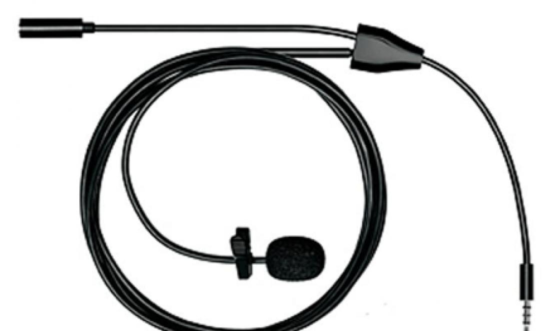
Choke in power supply with burnt wire
I had to remember the old technology)
I took my favorite PWM controller, which used to be installed in DVDs, receivers, adapters... 5H0165R.


Transformer ( 1
The electronic circuit serves to rectify the alternating voltage (converting it into direct voltage) and stabilize the output voltage at 12 V.

On the circuit diagram T1 – transformer. Typical transformer malfunctions are burnout or breakage of the wire of the primary winding, less often the secondary winding. As a rule, the primary, network winding is faulty ( 1 ).
The resistance of the primary winding should be several kilo-ohms (1 kOhm = 1000 Ohms), the secondary winding should be several tens of Ohms.

25.5 Ohm , which is also normal.
C1 (100uF 16V) 470 µF (25V)
AC power adapters - miniature power supplies for various electronic household equipment are used to power antenna amplifiers, radiotelephones, chargers. Despite the active introduction of switching power supplies, transformer power supplies are still actively used and are used in the user’s everyday life.
It is not uncommon for these transformer units to fail or break.
If the adapter breaks, you can replace it with a new one, the cost is low. But why give your hard-earned money if in most cases you can fix the problem yourself within 15 to 30 minutes and save yourself from searching for a replacement and wasting money?
So, let’s look at the composition of a conventional low-power power supply and its repair.
An adapter for 12V and a current of 100mA with a power of 3.6 Watts from the antenna amplifier came to the repair table.
The photo shows the adapter after the repair.

What parts does a typical transformer adapter consist of?
If we disassemble the adapter, we will find a transformer inside ( 1 ) and small electronic circuit (2 ).
Transformer ( 1 ) serves to reduce the 220V alternating mains voltage to the level of 13 - 15 V.
The electronic circuit serves to rectify the alternating voltage (converting it into direct voltage) and stabilize the output voltage at 12 V.
It's simple. What can break in such a simple device?
Let's take a look at the circuit diagram of this adapter.
On schematic diagram T1 – transformer. Typical transformer malfunctions are burnout or breakage of the wire of the primary winding, less often the secondary winding. As a rule, the primary, network winding is faulty ( 1 ).
The cause of a break or burnout is a thin wire that cannot withstand network surges and overloads. Let's say thank you to the Chinese, they are frugal guys, they don't want to run thicker wires...
Checking the health of the transformer is quite simple. It is necessary to measure the resistance of the primary and secondary windings. The resistance of the primary winding should be several kilo-ohms (1 kOhm = 1000 Ohms), the secondary winding should be several tens of Ohms.
When checking the adapter transformer for the primary winding, the resistance turned out to be 1.8 kOhm, which indicates that the primary winding is working properly.
For the secondary winding the resistance was 25.5 Ohm , which is also normal.
If there is no indication, you should measure the resistance of the primary winding of the transformer. This is easy to do; you don’t even have to disassemble the power supply, but measure the winding resistance through the contacts of the power plug.
We disassemble the power supply and perform an external inspection. Please pay attention to the darkened areas around the radio components, chips and cracks on the housings of the power stabilizer (78L12), and swelling of the filter capacitors.
During the repair of the antenna adapter, it turned out that the 78L12 stabilizer chip was faulty. The electrolytic capacitor was also replaced C1 (100uF 16V) to a capacitor with a larger capacity - 470 µF (25V) . When replacing a capacitor, the polarity of the capacitor must be taken into account.
It is not necessary to know the pinout (location and purpose) of the terminals of the 78L12 stabilizer; you must either remember, sketch or photograph the location of the faulty microcircuit on electronic board and solder a working part as soon as you find it. This simple operation will save your time if you soldered a faulty microcircuit, but a replacement was not found in time and you forgot how the microcircuit was soldered.
A switching power supply is built into most household appliances. As practice shows, this particular unit quite often fails, requiring replacement.
The high voltage constantly passing through the power supply does not in the best possible way affects its elements. And the point here is not the mistakes of the manufacturers. By increasing the service life by installing additional protection, you can achieve the reliability of the protected parts, but lose it on newly installed ones. In addition, additional elements complicate repairs - it becomes difficult to understand all the intricacies of the resulting circuit.
Manufacturers solved this problem radically by reducing the cost of the UPS and making it monolithic and non-separable. Such disposable devices are becoming more common. But, if you are lucky - the collapsible unit has failed, independent repair is quite possible.
The operating principle of all UPSs is the same. The differences relate only to the diagrams and types of parts. Therefore, understanding the breakdown, having basic knowledge of electrical engineering, is quite simple.
For repairs you will need a voltmeter.
It is used to measure the voltage across an electrolytic capacitor. It is highlighted in the photo. If the voltage is 300 V, the fuse is intact and all other elements associated with it (surge filter, power cable, input) are in good order.
There are models with two small capacitors. In this case, the normal functioning of the mentioned elements is indicated by a constant voltage of 150 V on each of the capacitors.
If there is no voltage, you need to ring the diodes of the rectifier bridge, the capacitor, the fuse itself, and so on. The tricky thing about fuses is that, if they fail, they look no different from working samples. A fault can only be detected through a continuity test - a blown fuse will show high resistance.
Having discovered a faulty fuse, you should carefully inspect the board, since it often fails simultaneously with other elements.
A damaged capacitor is easy to notice with the naked eye - it will be destroyed or swollen.
In this case, he does not need to be called, but simply disappears. The following elements are also soldered and ringed:
- power or rectifier bridge (looks like a monolithic block or can consist of four diodes);
- filter capacitor (looks like a large block or several blocks connected in parallel or in series), located in the high-voltage part of the block;
- transistors installed on the radiator (these are power switches).
Important. All parts are desoldered and replaced at the same time! Replacing one at a time will lead to burnout of the power unit each time.
Burnt out elements must be replaced with new ones. The radio market offers a wide range of parts for power supplies. It’s quite easy to find good options at minimal prices.
Just a note. The fuse can be successfully replaced with a piece of copper wire. A wire thickness of 0.11 millimeters corresponds to a 3 Ampere fuse.
Causes of failure:- voltage fluctuations;
- lack of protection (there is space for it, but the element itself is not installed - this is how manufacturers save money).
Solution this malfunction of switching power supplies:
- install protection (it is not always possible to select the right part);
- or use a mains voltage filter with good protective elements (not jumpers!).
What to do if there is no output voltage?
Another common cause of power supply failure has nothing to do with the fuse. We are talking about the absence of output voltage when such an element is fully operational.
Solving the problem:
- Swollen capacitor - requires desoldering and replacement.
- A failed inductor - it is necessary to remove the element and change the winding. The damaged wire is unwound. At the same time, the turns are counted. Then a new suitable wire is wound at the same number of turns. The part is returned to its place.
- Deformed bridge diodes are replaced with new ones.
- If necessary, parts are checked by a tester (if no damage is visually detected).
Before that, it is necessary to study the rules for the safe use of such a tool. You should not shine such a device into reflective surfaces, as this can damage your eyes.
It is quite possible to build it yourself. A fan is used as a blower, and a coil is used as a heater. The best option is a circuit with a thyristor.
Causes of failure:
- poor ventilation.
Solution:
- do not cover ventilation openings;
- ensure optimal temperature conditions - cooling and ventilation.
What you need to remember:
- The first connection of the unit is made to a 25 Watt lamp. This is especially important after replacing diodes or transistors! If an error is made somewhere or a malfunction is not noticed, the passing current will not damage the entire device as a whole.
- When starting work, do not forget that a residual discharge remains on electrolytic capacitors for a long time. Before soldering the parts, it is necessary to short-circuit the capacitor leads. You can't do this directly. It is necessary to short-circuit through a resistance rated higher than 0.5 V.
If the entire UPS has been thoroughly checked, but still does not work, you can contact a repair shop. Perhaps your case relates to a complex breakdown that is still fixable.
According to statistics, about 5% of breakdowns require unit replacement. Fortunately, this device is always available. In stores you can find a rich assortment in different price categories.
The switching power supply is built into most household appliances. As practice shows, this particular unit quite often fails, requiring replacement.
The high voltage constantly passing through the power supply does not have the best effect on its elements. And the point here is not the mistakes of the manufacturers. By increasing the service life by installing additional protection, you can achieve the reliability of the protected parts, but lose it on newly installed ones. In addition, additional elements complicate repairs - it becomes difficult to understand all the intricacies of the resulting circuit.
Manufacturers solved this problem radically by reducing the cost of the UPS and making it monolithic and non-separable. Such disposable devices are becoming more common. But, if you are lucky - the collapsible unit has failed, independent repair is quite possible.
The operating principle of all UPSs is the same. The differences relate only to the diagrams and types of parts. Therefore, understanding the breakdown, having basic knowledge of electrical engineering, is quite simple.
For repairs you will need a voltmeter.
It is used to measure the voltage across an electrolytic capacitor. It is highlighted in the photo. If the voltage is 300 V, the fuse is intact and all other elements associated with it (mains filter, power cable, input) are in good order.
There are models with two small capacitors. In this case, the normal functioning of the mentioned elements is indicated by a constant voltage of 150 V on each of the capacitors.
If there is no voltage, you need to ring the diodes of the rectifier bridge, the capacitor, the fuse itself, and so on. The tricky thing about fuses is that, if they fail, they look no different from working samples. A fault can only be detected through a continuity test - a blown fuse will show high resistance.
Having discovered a faulty fuse, you should carefully inspect the board, since it often fails simultaneously with other elements.
A damaged capacitor is easy to notice with the naked eye - it will be destroyed or swollen.
In this case, he does not need to be called, but simply disappears. The following elements are also soldered and ringed:
- power or rectifier bridge (looks like a monolithic block or can consist of four diodes);
- filter capacitor (looks like a large block or several blocks connected in parallel or in series), located in the high-voltage part of the block;
- transistors installed on the radiator (these are power switches).
Important. All parts are desoldered and replaced at the same time! Replacing one at a time will lead to burnout of the power unit each time.
Burnt out elements must be replaced with new ones. The radio market offers a wide range of parts for power supplies. It’s quite easy to find good options at minimal prices.
Just a note. The fuse can be successfully replaced with a piece of copper wire. A wire thickness of 0.11 millimeters corresponds to a 3 Ampere fuse.
Causes of failure:- voltage fluctuations;
- lack of protection (there is space for it, but the element itself is not installed - this is how manufacturers save money).
Solution this malfunction of switching power supplies:
- install protection (it is not always possible to select the right part);
- or use a mains voltage filter with good protective elements (not jumpers!).
What to do if there is no output voltage?
 Another common cause of power supply failure has nothing to do with the fuse. We are talking about the absence of output voltage when such an element is fully operational.
Solving the problem:
- Swollen capacitor - requires desoldering and replacement.
- A failed inductor - it is necessary to remove the element and change the winding. The damaged wire is unwound. At the same time, the turns are counted. Then a new suitable wire is wound at the same number of turns. The part is returned to its place.
- Deformed bridge diodes are replaced with new ones.
- If necessary, parts are checked by a tester (if no damage is visually detected).
Before that, it is necessary to study the rules for the safe use of such a tool. You should not shine such a device into reflective surfaces, as this can damage your eyes.
It is quite possible to build it yourself. A fan is used as a blower, and a coil is used as a heater. The best option is a circuit with a thyristor.
Causes of failure:
- poor ventilation.
Solution:
- do not cover ventilation openings;
- provide optimal temperature regime– cooling and ventilation.
What you need to remember:
- The first connection of the unit is made to a 25 Watt lamp. This is especially important after replacing diodes or transistors! If an error is made somewhere or a malfunction is not noticed, the passing current will not damage the entire device as a whole.
- When starting work, do not forget that a residual discharge remains on electrolytic capacitors for a long time. Before soldering the parts, it is necessary to short-circuit the capacitor leads. You can't do this directly. It is necessary to short-circuit through a resistance rated higher than 0.5 V.
If the entire UPS has been thoroughly checked, but still does not work, you can contact a repair shop. Perhaps your case relates to a complex breakdown that is still fixable.
According to statistics, about 5% of breakdowns require unit replacement. Fortunately, this device is always available. In stores you can find a rich assortment in different price categories.
Features of repairing a DVD switching power supply on video
In most modern electronic devices Analogue (transformer) power supplies are practically not used; they are replaced by pulsed voltage converters. To understand why this happened, it is necessary to consider the design features, as well as the strengths and weaknesses of these devices. We will also talk about the purpose of the main components of pulsed sources and give a simple example of an implementation that can be assembled with your own hands.
Design features and operating principle
Of the several methods of converting voltage to power electronic components, two that are most widespread can be identified:
- Analog, the main element of which is a step-down transformer, in addition to its main function, it also provides galvanic isolation.
- Impulse principle.
Let's look at how these two options differ.
PSU based on a power transformer
Let's consider a simplified block diagram of this device. As can be seen from the figure, a step-down transformer is installed at the input, with its help the amplitude of the supply voltage is converted, for example, from 220 V we get 15 V. The next block is a rectifier, its task is to convert the sinusoidal current into a pulsed one (the harmonic is shown above the symbolic image). For this purpose, rectifying semiconductor elements (diodes) connected via a bridge circuit are used. Their operating principle can be found on our website.
The next block performs two functions: it smoothes the voltage (a capacitor of appropriate capacity is used for this purpose) and stabilizes it. The latter is necessary so that the voltage does not “drop” when the load increases.
The given block diagram is greatly simplified; as a rule, a source of this type has an input filter and protective circuits, but this is not important for explaining the operation of the device.
All the disadvantages of the above option are directly or indirectly related to the main design element - the transformer. Firstly, its weight and dimensions limit miniaturization. In order not to be unfounded, we will use as an example a step-down transformer 220/12 V with a rated power of 250 W. The weight of such a unit is about 4 kilograms, dimensions 125x124x89 mm. You can imagine how much a laptop charger based on it would weigh.
Secondly, the price of such devices is sometimes many times higher than the total cost of the other components.
Pulse devices
As can be seen from the block diagram shown in Figure 3, the operating principle of these devices differs significantly from analog converters, primarily in the absence of an input step-down transformer.
 Figure 3. Block diagram of a switching power supply
 Let's consider the operating algorithm of such a source:
- Power is supplied to the network filter; its task is to minimize network noise, both incoming and outgoing, that arises as a result of operation.
- Next, the unit for converting sinusoidal voltage into pulsed constant voltage and a smoothing filter come into operation.
- At the next stage, an inverter is connected to the process; its task is related to the formation of rectangular high-frequency signals. Feedback to the inverter is carried out through the control unit.
- The next block is IT, it is necessary for automatic generator mode, supplying voltage to the circuit, protection, controller control, as well as the load. In addition, the IT task includes ensuring galvanic isolation between high and low voltage circuits.
Unlike a step-down transformer, the core of this device is made of ferrimagnetic materials, this contributes to the reliable transmission of RF signals, which can be in the range of 20-100 kHz. A characteristic feature of IT is that when connecting it, the inclusion of the beginning and end of the windings is critical. The small dimensions of this device make it possible to produce miniature devices; an example is the electronic harness (ballast) of an LED or energy-saving lamp.

- Next, the output rectifier comes into operation, since it works with high-frequency voltage; the process requires high-speed semiconductor elements, so Schottky diodes are used for this purpose.
- At the final phase, smoothing is performed on an advantageous filter, after which voltage is applied to the load.
Now, as promised, let’s look at the operating principle of the main element of this device – the inverter.
How does an inverter work?
RF modulation can be done in three ways:
- pulse-frequency;
- phase-pulse;
- pulse width.
In practice, the last option is used. This is due both to the simplicity of implementation and to the fact that PWM has a constant communication frequency, unlike the other two modulation methods. A block diagram describing the operation of the controller is shown below.
The operating algorithm of the device is as follows:
The reference frequency generator generates a series of rectangular signals, the frequency of which corresponds to the reference one. Based on this signal, a sawtooth U P is formed, which is supplied to the input of the comparator K PWM. The UUS signal coming from the control amplifier is supplied to the second input of this device. The signal generated by this amplifier corresponds to the proportional difference between U P (reference voltage) and U RS (control signal from the feedback circuit). That is, the control signal UUS is, in fact, a mismatch voltage with a level that depends on both the current on the load and the voltage on it (U OUT).
This implementation method allows you to organize a closed circuit that allows you to control the output voltage, that is, in fact, we are talking about a linear-discrete functional unit. Pulses are generated at its output, with a duration depending on the difference between the reference and control signals. Based on it, a voltage is created to control the key transistor of the inverter.
The process of stabilizing the output voltage is carried out by monitoring its level; when it changes, the voltage of the control signal U PC changes proportionally, which leads to an increase or decrease in the duration between pulses.
As a result, the power of the secondary circuits changes, which ensures stabilization of the output voltage.
To ensure safety, galvanic isolation between the power supply and feedback is required. As a rule, optocouplers are used for this purpose.
Strengths and weaknesses of pulsed sources
If we compare analog and pulse devices the same power, then the latter will have the following advantages:
- Small size and weight due to the absence of a low-frequency step-down transformer and control elements that require heat removal using large radiators. Thanks to the use of high-frequency signal conversion technology, it is possible to reduce the capacitance of the capacitors used in the filters, which allows the installation of smaller elements.
- More high efficiency, since the main losses are caused only by transient processes, while in analog circuits a lot of energy is constantly lost during electromagnetic conversion. The result speaks for itself, increasing efficiency to 95-98%.
- Lower cost due to the use of less powerful semiconductor elements.
- Wider input voltage range. This type of equipment is not demanding on frequency and amplitude; therefore, connection to networks of various standards is allowed.
- Availability of reliable protection against short circuits, overload and other emergency situations.
The disadvantages of pulse technology include:
The presence of RF interference is a consequence of the operation of the high-frequency converter. This factor requires the installation of a filter that suppresses interference. Unfortunately, its operation is not always effective, which imposes some restrictions on the use of devices of this type in high-precision equipment.
Special requirements for the load, it should not be reduced or increased. As soon as the current level exceeds the upper or lower threshold, the output voltage characteristics will begin to differ significantly from the standard ones. As a rule, manufacturers (in lately even Chinese) provide for such situations and install appropriate protection in their products.
Scope of application
Almost all modern electronics are powered from blocks of this type; examples include:


Assembling a switching power supply with your own hands
Let's consider the circuit of a simple power supply, where the above-described operating principle is applied.

Designations:
- Resistors: R1 – 100 Ohm, R2 – from 150 kOhm to 300 kOhm (selectable), R3 – 1 kOhm.
- Capacitances: C1 and C2 – 0.01 µF x 630 V, C3 -22 µF x 450 V, C4 – 0.22 µF x 400 V, C5 – 6800-15000 pF (selectable), 012 µF, C6 – 10 µF x 50 V, C7 – 220 µF x 25 V, C8 – 22 µF x 25 V.
- Diodes: VD1-4 - KD258V, VD5 and VD7 - KD510A, VD6 - KS156A, VD8-11 - KD258A.
- Transistor VT1 – KT872A.
- Voltage stabilizer D1 - microcircuit KR142 with index EH5 - EH8 (depending on the required output voltage).
- Transformer T1 - a w-shaped ferrite core with dimensions 5x5 is used. The primary winding is wound with 600 turns of Ø 0.1 mm wire, the secondary (pins 3-4) contains 44 turns of Ø 0.25 mm, and the last winding contains 5 turns of Ø 0.1 mm.
- Fuse FU1 – 0.25A.
The setup comes down to selecting the values of R2 and C5, which ensure excitation of the generator at an input voltage of 185-240 V.