Hi all! I would like to bring to your attention a simple propeller clock that I assembled on the Atmega8 controller. They are made from readily available parts and are easy to replicate and manufacture. The only thing is that you need a programmer to flash the clock controller and control panel.
A regular 120 mm fan (cooler) was used for the base of the clock. You can use any fans for this clock, both clockwise and counter-clockwise, because while I was assembling this clock, I modified the program a little and switched the display of symbols from the remote control programmatically.
The circuitry of the clock itself is quite simple and is assembled on an Atmega8 microcontroller, to synchronize its operation a clock quartz with a frequency of 32768 Hz is used.
The clock is powered by a receiving coil, the energy to which is transferred from a generator with a transmitting coil. Both of these coils make up an air transformer.

There were no particular problems with the circuit and design of the generator, since a generator from a plasma ball was used.

The generator is assembled on the common TL494 microcircuit and allows you to change the width and frequency of the output pulses over a wide range.
Even with a gap of a centimeter between the coils, the voltage is quite enough to start the clock. Just take into account that the larger the gap between the coils, the larger the pulse width needs to be made and, accordingly, the current consumption from the source increases.

When turning on the generator for the first time, set the pulse width (duty factor) to a minimum (the control knob is in the upper position according to the diagram, that is, leg 4 is pulled through resistor R7 to leg 14, 15, 2 of the TL-494). We turn the generator frequency until the squeak disappears, this is approximately 18-20 KHz (tuning by ear), and if there is something to measure the frequency, then we adjust it accordingly within these limits.
The generator board also contains an additional voltage regulator on LM317, designed to regulate the fan speed.
It’s not on the diagram, I didn’t draw it
. Watch a demo video of the clock in action.
Video.
The clock board itself is attached to the base of the fan. I secured it with double-sided tape.

Then I slightly modified the clock circuit from a photoresistor to an infrared photodiode (picture below).
In the transmitter instead simple LED, I now have infrared.
The resistor was set to 100k instead of 2k.

The critical moments in the manufacture of a clock are the manufacture of an air transformer and alignment (or rather balancing) of the clock board on the base of the fan.
Take these moments more seriously.
Air transformer.
It was based on a regular 120 mm cooler with bronze bushings. The clock board is glued to the base with double-sided tape.
We bite off the blades from the cooler and grind and level them with a file and sandpaper. The coils are made on a frame made of cable duct. I didn’t come up with this design, I just took this idea from the internet. To wind the transformer, a base is made from a cable channel. Every 5 mm we make a cut on the sides of the channel and carefully roll it into a circle; select the diameter so that it fits tightly on the plastic base of the fan.

Next, we wind 100 turns of enameled wire with a diameter of 0.25 onto the mandrel from the cable channel.
The current consumption of the assembled transformer turned out to be 200 mA (this is with a fairly noticeable gap between the coils).
In general, together with the fan motor, the current consumption is around 0.4-0.5A.
We do the same for the primary (transmitting) coil, but we try to make a minimum gap between the coils. The transmitting coil also contains 100 turns of 0.3 wire (or 0.25).
In the diagram I have slightly different winding data for these coils.

Hours fee.
The strip with LEDs is made on fiberglass. A hole is drilled in it, a piece of tube from a telescopic antenna is inserted into this hole and soldered to the board (the antenna tube must be cleaned of the shiny coating). You can use any suitable tube, or attach the board in another way, for example using a screw with nuts.
I connected the board with LEDs to the clock board with a regular enameled (winding) wire; it is more rigid than the mounting wire and does not fray when rotated.

To balance the entire board, on the other side we glue a screw with a diameter of 3-4 mm with hot glue, screwing various nuts onto the screw on the other side - we achieve minimal vibration.
To check the functionality of the clock board, we short-circuit the photoresistor with a screwdriver or tweezers; the LEDs should blink.
The clock starts working when 5V (logical unit) appears on the 5th leg of the atmega. That is, when the photoresistor is illuminated, there should be 5V on the 5th leg,
When the photoresistor is not illuminated, there should be a logical 0 (about 0V) on the 5th leg of the atmega, for this we select a resistor to ground from the 5th leg. The diagram shows 2 kOhm, I got 2.5 Kohm.
At the bottom of the fan base we glue an LED so that with each revolution of the fan motor, the photoresistor passes as close as possible to the light source (LED).
Control panel.
The control panel is designed to control the operation of the clock, switch display modes (change the direction of fan rotation), and set the clock time.
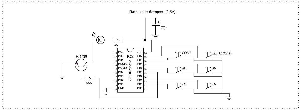
The remote control circuit is assembled on an ATTINY2313 microcontroller. The board contains the MK itself with a harness and six buttons designed to control the clock.

I didn’t assemble the housing for the remote control, so only a photo of the board itself.

Information on the purpose of the remote control buttons;
H+ and H- clock settings
M+ and M- minutes setting
R/L change of direction (for screws rotating clockwise and counterclockwise)
font change font (thin, bold and website inscription)
When writing a site, use the H+ and H - buttons to adjust the width of the inscription.
The attached archive contains all the necessary files for assembling the watch;
Archive for the article
If you have any questions about the design of the watch, ask them on the forum, I will try to help and answer your questions as much as possible.
Electrical circuit diagram

One device combines two functions: the actual measurement of temperature and time (clock). The display is performed alternately, changing every ten seconds. To set the clock, two buttons are used, similar to a simple Chinese electronic clock: one is responsible for selecting a parameter, the second for changing it. The device is powered from the network using a constant stabilized current source of five volts (board from the phone charger).


The temperature sensor is a DS18B20 chip. Since the Clock-Thermometer device does not have its own battery, if the power is lost, the readings will naturally be lost. And so that this does not cause a person to be late for vital matters, there is an interesting “trick” - when power is applied, dashes will be displayed on the display instead of time until you press one of the two setting buttons.


The body of the homemade temperature meter was a suitable cufflink box. The clock-thermometer board itself and the board taken out from the telephone charger were placed in it. The DS18B20 sensor is made remote and connected via a connector.


List of required parts
- Atmega8 microcontroller - 1 pc.
- Quartz 32768 Hz - 1 pc.
- Temperature sensor DS18B20 - 1 pc.
- Seven segment indicator (4 digits) - 1 pc.
- SMD resistors size 0805:
- 620 Ohm - 8 pcs.
- 0 Ohm (jumper) - 1 pc.
- 4.7 kOhm - 1 pc.
- Tact buttons - 2 pcs.
Video of the device on YouTube channel
I bring to your attention a simple diagram and design “ Two-channel thermometer, clock on ATmega8, DS18B20, DS1307, LCD (ZhK) 1602«.
The design allows you to display the current time, date, month, day of the week and current temperature from two digital temperature sensors on a two-line symbol indicator.
Diagram of a two-channel thermometer and clock
The design is assembled on an ATmega8-16PU microcontroller, a DS1307 real-time clock chip in a DIP package, DS18B20 digital temperature sensors, and an LCD1602 LCD indicator

The device diagram was created in the program
Temperature sensors are connected to connectors DS1 and DS2:
— pin 1 — to the GND pin of the sensor
— pin 2 — to the DQ pin of the sensor
— pin 3 — to the Vcc pin of the sensor
The sensor connections in the diagram do not correspond to the printed circuit board.
The program is tailored to the printed circuit board, you need to connect:
— 1st sensor to PB1 (15th pin)
— 2nd sensor to PB2 (16th pin)
I draw your attention to connecting the pins of port D of the microcontroller to the pins of the indicator:
- PD0 of the microcontroller - to pin D7 of the indicator
- PD1 of the microcontroller - to pin D6 of the indicator
- PD2 of the microcontroller - to pin D5 of the indicator
- PD3 of the microcontroller - to pin D4 of the indicator
This connection was chosen to simplify the layout of tracks on the printed circuit board.
Details used in the design:

The LCD display is 2-line, 16-character negative, white characters on a dark blue background with white backlighting. You can also use any similar character-synthesizing (symbolic) two-line, 16-character indicator, with or without Cyrillic support, that supports the command system of the HD44780 type controller:
— STN (FSTN) Negative (blue or black) with backlight (this is used in the design) — such indicators only work with backlight
— FSTN Positive, TN Positive, HTN Positive — with or without backlight
The Chinese LCD indicator used does not have a built-in Cyrillic alphabet, therefore, for clarity of displaying the day of the week on the indicator, custom characters are written into the character generator RAM (CGRAM) - “P”, “n”, “t”, “Ch”, “b” and two characters in inverse form “D” and “U”.
Printed circuit board of a two-channel thermometer and clock
The design is assembled on a single-sided printed circuit board, all used parts are “output”
The device's printed circuit board was created in the program.
There are three jumpers on the board - P1, P2, P3
The quartz resonator is installed “lying” on the board; the resonator body is soldered with a jumper to the contact pad on the board under the resonator.

Description of the operation of a two-channel thermometer and clock
The basis of the design "D" two-channel thermometer, clock" is a microcontroller ATmega8 in DIP package with clock frequency 1 MHz from built-in oscillator with internal RC circuit. Setting FUSE bits is the default, no need to change anything.
A real-time clock chip is used to determine the current time DS1307, which counts seconds, minutes, hours, date of month, month, day of week and year with leap year compensation valid until 2100.
Only the following are displayed:
- current time - hours and minutes
- date of month
- month
- day of the week
Two digital temperature sensors are used as temperature sensors DS18В20, which allow you to measure the current temperature ranging from -45 degrees to +125 degrees Celsius with an accuracy of 0.5 degrees.
The current temperature of each sensor is displayed with a resolution of 0.1 °C
Before the value of each temperature, the symbols “D” and “U” are displayed in inverse form:
- “D” - temperature in the house
— “U” — outside temperature

The program's operation is organized by overflow interrupts from timer T1 occurring every 4 seconds. The current time is updated every 4 seconds, the current temperatures from the sensors are updated alternately, every 4 seconds.
The device is powered from a stabilized 5 Volt power source, you can use charger from cell phone, or an autonomous power source - battery. The current consumption depends on the brightness of the backlight (the value of resistor R3) and in a particular case is 12 mA.
The device is controlled by two buttons:
— S1 — “Selection”
— S2 — “Installation”
When the device is turned on for the first time (or every time it is turned on in the absence of a backup power supply DS1307 - BAT1), the device goes into the “Full” installation mode. In this case, it is necessary to set the current year, month, date, day of the week and current time - hours and minutes. In this mode, the explanatory information was not translated into Russian (unlike the day of the week indication), all explanations are displayed in English (a complete installation is performed extremely rarely, it is not difficult to understand):
Setting the Year:
A blinking cursor in the form of a white rectangle indicates where and what needs to be entered:
— with the “Install” button — we set it to tens of years
- using the “Select” button - proceed to setting the year units
— using the “Setup” button — set the value of the year units
— with the “Select” button — go to the next setting
 Setting the month to “Month”
- similar to setting the year
 Setting the day of the month “Data”:
- similar to setting the year
 Setting the day of the week “Week”:
- similar to setting the year, with - 1 - Mon, 2 - Tue, 3 - Wed, 4 - Thu, 5 - Fri, 6 - Sat, 7 - Sun
 Setting the current time “Hour_Min”
For example, the current time is 17 hours 39 minutes:
— with the “Install” button — we set tens of hours — 1
— using the “Select” button — proceed to setting the hour units
— using the “Setup” button — set the hour units — 7
— using the “Select” button — go to setting tens of minutes — 4
— using the “Setup” button — set the minutes units to -0
— the seconds are already indicated on the displays as “00”
— at exactly 17 hours 40 minutes press the “Select” button and the current time 17 hours 40 minutes 00 seconds will be recorded in DS1307

In operating mode, the “Select” and “Install” buttons allow you to switch to the following modes:
— Select button— time correction (in this case, only the current time “Hour_Min” is set as described above)
— "Install" button— “Full” installation
To login desired mode you must press the corresponding button and hold it until the display screen clears. After clearing the display, release the button and after a second we go to the selected mode.
The design was developed and tested on a breadboard; it was not assembled in hardware.
There have been many comments about the device not working, inconsistency printed circuit board scheme.
It was decided to recreate the device in hardware.
Below are photographs of the assembled device according to the circuit, printed circuit board and firmware published on this page.
The device started working immediately, no problems observed.
The printed circuit board is made using the LUT method. Due to an error in installing the microcircuits on the board, they had to be desoldered and rearranged (and there is a hole in the old woman), which led to damage to the printed circuit conductors and, as a result, - appearance not very good, jumper P2 is installed on the side of the printed circuit conductors (did not drill holes), sensor DS1 is connected with a cable about 1 meter long (so that it is at a height of about 30 cm from the floor, sensor DS2 is connected with a cable 5 meters long and placed outside the window. The connectors for connecting sensors were taken from coolers of old computers.
There was one problem - the RTC DS1307 did not start right away, the reason was rosin between the quartz pins. After washing the board, the clock started working.


(10.8 KiB, 1,995 hits)
(27.3 KiB, 1,473 hits)
(390.1 KiB, 1,296 hits)
(51.7 KiB, 2,494 hits)
Download from YandexDisk (additionally - datasheets in Russian)
You can order all the necessary parts for assembling a “Dual-channel thermometer, clock on ATmega8, DS18B20, Ds1307”, including a programmed microcontroller at online store site
This electronic clock, built on the Atmega8 microcontroller, is equipped with an easy-to-read LED display, an alarm clock with a snooze function, and a power recovery function.
Watch specifications
- time display format: hours, minutes;
- alarm clock with snooze function;
- simple control using 2 buttons;
- Battery operation support;
- supply voltage: 7…12V / 0.2 A;
- dimensions of two printed circuit boards: 60×21 mm, 58×44 mm.
The schematic diagram of the clock is shown in the figure below. The clock circuit must be powered with a constant voltage in the range of 7...12V. This can be any with a current load of at least 200 mA.
You can connect a buzzer with a generator to the CON5 connector of the board, which will act as sound signal alarm clock Buttons are connected to terminals SA1 and SA2 of the printed circuit board, which are used to enter settings and operate the clock.

Setting the time and alarm
When you press the SA1 button, we get to the “Set1” clock menu, where we have the ability to set the current time, and another short press of the SA1 button takes us to the “Set2” alarm time setting menu.
To select and change settings, use the SA2 button. After selecting both in the time setting mode and in the alarm setting mode, the first digit will begin to flash on the display, after which you can set dozens of hours using the SA2 button.
Pressing SA1 again will cause the second digit to blink and using SA2 you can set the hour units. The next two presses of SA1 will allow you to set tens of minutes and units of minutes. When setting the hours and minutes, only one digit is always set. Pressing SA1 a fifth time returns the watch to normal operation. Also, a long period of time without pressing any buttons will terminate the installation procedures.
While the clock is running, long pressing the SA2 button turns the alarm on/off. When the alarm is activated, the start time is displayed for a few seconds. The alarm status is indicated by a dot located in the fourth digit. When the alarm is active, this indicator lights up.
After turning on the alarm, you can press any button to turn it off for about 5 minutes, and the snooze function will be activated. This fact is indicated by a flashing dot on the fourth digit of the indicator. After 5 minutes, the alarm will sound again. By pressing any button again, it can be postponed for another 5 minutes, etc.
The alarm signal is completely turned off after a long press of the SA2 key, or about a minute and a half of no reaction from the user.
The clock operation has been tested in Proteus:

If during operation of the watch it turns out that the watch is significantly behind or in a hurry, you can try to reduce or increase the value of capacitor C1.
(34.7 Kb, downloads: 1,931)