This was briefly discussed universal device. The information provided is enough to make the measurement process conscious, but in the case of repairing such a complex device, more in-depth knowledge will be needed, because the circuitry of electronic oscilloscopes is very diverse and quite complex.
Most often, a beginning radio amateur has a single-beam oscilloscope at his disposal, but having mastered the techniques of using such a device, it will not be difficult to switch to a dual-beam or digital oscilloscope.
Figure 1 shows a fairly simple and reliable oscilloscope S1-101, which has such a small number of knobs that it is absolutely impossible to get confused in them. Please note that this is not some kind of oscilloscope for school physics lessons; this is exactly what was used in production just twenty years ago.
The oscilloscope's power supply is not only 220V. Possible power supply DC 12V, for example a car battery, which allows you to use the device in the field.
Figure 1. Oscilloscope S1-101
Auxiliary adjustments
On top panel The oscilloscope contains knobs for adjusting the brightness and focusing of the beam. Their purpose is clear without explanation. All other controls are located on the front panel.
Two controls, indicated by arrows, allow you to adjust the position of the beam vertically and horizontally. This allows you to more accurately align the signal image on the screen with the coordinate grid to improve the counting of divisions.
The zero voltage level is located on the center line of the vertical scale, which allows you to observe a bipolar signal without a constant component.
To study a unipolar signal, for example, digital circuits, it is better to move the beam to the lower division of the scale: you get one vertical scale of six divisions.
The front panel also contains a power switch and a power indicator.
Signal Boost
The “V/div” switch sets the sensitivity of the vertical deflection channel. The Y channel gain is calibrated, changes in steps of 1, 2, 5, there is no smooth sensitivity adjustment.
By rotating this switch, you should ensure that the swing of the pulse under study is at least 1 division of the vertical scale. Only then can stable signal synchronization be achieved. In general, you should strive to get the signal range as large as possible, as long as it does not go beyond the coordinate grid. In this case, the measurement accuracy increases.
In general, a recommendation for selecting gain could be as follows: turn the switch counterclockwise to the 5V/div position, then rotate the knob clockwise until the signal swing on the screen becomes the same as recommended in the previous paragraph. It's like: if the value of the measured voltage is unknown, start measurements from the highest voltage range.
The most recent clockwise position of the vertical sensitivity switch is indicated by a black triangle labeled “5DIV.” In this position, rectangular pulses with a swing of 5 divisions appear on the screen, the pulse frequency is 1 KHz. The purpose of these pulses is to check and calibrate the oscilloscope. In connection with these impulses, a somewhat comical incident comes to mind, which can be told as an anecdote.
One day a friend came to our workshop and asked to use an oscilloscope to set up some kind of homemade design. After several days of creative torment, we hear the following exclamation from him: “Oh, you turned off the power, but the impulses are so good!” It turned out that, out of ignorance, he simply turned on calibration pulses, which are not controlled by any knobs on the front panel.
Open and closed entrance
Directly below the sensitivity switch is a three-position switch for operating modes, often referred to as " open entrance" and "closed". In the extreme left position of this switch, it is possible to measure DC and AC voltages with a DC component.
In the right position, the input of the vertical deflection amplifier is connected through a capacitor, which does not allow the DC component to pass through, but you can see the variable, even if the DC component is far from 0V.
An example of the use of a closed entrance is the following: practical problem, as measuring the ripple of a power source: the output voltage of the source is 24V, and the ripple should not exceed 0.25V.
Assuming that the voltage is 24V and the sensitivity of the vertical deflection channel is 5V/div. takes almost five scale divisions (zero will have to be set to the lowest line of the vertical scale), then the beam will fly to the very top, and pulsations of tenths of a volt will be practically unnoticeable.
To accurately measure these ripples, simply switch the oscilloscope to closed input mode, place the beam in the center of the vertical scale and select a sensitivity of 0.05 or 0.1 V/div. In this mode, pulsation measurement will be quite accurate. It should be noted that the DC component can be quite large: the closed input is designed to operate with a DC voltage of up to 300V.
In the middle position of the switch, the measuring probe is simply DISCONNECTED from the input of amplifier Y, which makes it possible to set the position of the beam without disconnecting the probe from the signal source.
In some situations this property is quite useful. The most interesting thing is that this position is marked on the oscilloscope panel with the icon of a common wire, ground. It seems that the test probe is connected to a common wire. And what will happen then?
In some oscilloscope models, the input mode switch does not have a third position; it is simply a button or toggle switch that switches open/closed input modes. It is important that in any case there is such a switch.
To preliminary assess the performance of the oscilloscope, just touch the signal (sometimes called hot) end of the measuring probe with your finger: network interference should appear on the screen in the form of a blurred beam. If the sweep frequency is close to the mains frequency, a blurred, torn and shaggy sine wave will appear. When you touch the “ground” end with your finger, naturally, there will be no interference on the screen.
Here you can remember one of the ways to check capacitors for breaks: if you take a working capacitor in your hand and touch the hot end with it, the same shaggy sine wave will appear on the screen. If the capacitor is broken, then no changes will occur on the screen.
Switch "Time/div." The sweep duration is set. When observing a periodic signal, rotate this switch to ensure that one or two periods of the signal are shown on the screen.

Figure 2.
The sweep synchronization knob of the S1-101 oscilloscope is indicated by just one word “Level”. In addition to this knob, the S1-73 oscilloscope has a “stability” knob (some feature of the sweep circuit); on some oscilloscopes this same knob is simply called “SYNC.” The use of this pen should be described in a little more detail.
How to achieve a stable signal image
When connecting to the circuit under test, the picture shown in Figure 3 most often appears on the screen.

Figure 3.
In order to obtain a stable image, you should turn the “Synchronization” knob, which is indicated as “Level” on the front panel of the S1-101 oscilloscope. For some reason, different oscilloscopes have different designations for controls, but in essence they are the same knob.

Figure 4. Image synchronization
To obtain a stable signal from the blurred image shown in Figure 19, just turn the “SYNC.” knob. or in our case “level”. When rotating counterclockwise until the minus sign, an image of the signal will appear on the screen, in this case a sinusoid, shown in Figure 20a. Synchronization begins on the falling edge of the signal.
When you rotate the same knob to the plus sign, the same sinusoid will look like in Figure 4b: the sweep starts on an ascending edge. The first period of the sine wave begins just above the zero line, this affects the start time of the sweep.
If the oscilloscope has a delay line, then such a loss will not occur. For a sinusoid, this may not be particularly noticeable, but when studying a rectangular pulse, you can lose the entire front of the pulse in the image, which in some cases is quite important. Especially when working with external scan.
Working with external scan
Next to the “LEVEL” regulator there is a toggle switch labeled “OUTSIDE/INSIDE”. In the “INTERNAL” position, the sweep starts from the signal being studied. It is enough to apply the signal under study to input Y and turn the “LEVEL” knob and a stable image will appear on the screen, as shown in Figure 4.
If the mentioned toggle switch is set to the “OUT” position, then it will not be possible to obtain a stable image by any rotation of the “LEVEL” knob. To do this, you need to send a signal that will synchronize the image to the external synchronization input. This input is located on the white plastic panel located to the right of the Y input.
There are also sockets for the sawtooth sweep voltage output (used to control various RCCs), a calibration voltage output (can be used as a pulse generator) and a common wire socket.
An example where external sweep operation may be required is the pulse delay circuit shown in Figure 5.

Figure 5. Pulse delay circuit on a 555 timer
When a positive pulse is applied to the input of the device, the output pulse appears with a delay determined by the parameters of the RC chain; the delay time is determined by the formula shown in the figure. But according to the formula, the value is determined very approximately.
If you have a dual-beam oscilloscope, determining the time is very simple: just apply both signals to different inputs and measure the pulse delay time. What if a dual-beam oscilloscope is not available? This is where the external scan mode comes to the rescue.
The first thing to do is to apply the input signal of the circuit (Fig. 5) to the external synchronization input and connect the Y input here. Then, by rotating the “LEVEL” knob, achieve a stable image of the input pulse, as shown in Fig. 5b. In this case, two conditions must be met: the “EXTERNAL/INTERNAL” toggle switch is set to the “EXTERNAL” position, and the signal under study should be periodic, and not single, as shown in Fig. 5.
After this, you need to remember the position on the screen of the input signal and apply the output signal to input Y. All that remains is to calculate the required delay by scale divisions. Naturally, this is not the only circuit where it may be necessary to determine the delay time between two pulses; there are a great many such circuits.
The next article will talk about the types of signals being studied and their parameters, as well as how to carry out different measurements using an oscilloscope.
Oscilloscope model C1 73 is the most common domestic device for monitoring the shape of electrical signals and measuring them technical parameters in its class (electron beam). It has a lot of advantages: reasonable price, simple design, small dimensions and good performance properties. It is these advantages of the signal meter that have made it popular among technicians and radio amateurs.
Purpose and general information
The S1 73 brand oscilloscope is intended for carrying out research procedures on electrical signals that have the following characteristics:
- frequency range – from 0 to 5 MHz;
- amplitude – from 20 mV to 120 V (if an external 1:10 divider is included in the package, the range of the measured amplitude increases to 350 V);
- the ability to measure electrical voltage of both direct and alternating types;
- time interval range – from 0.4 µs to 0.5 s.

The C1 73 oscilloscope is powered both from a 220 V mains voltage (the delivery package includes a rectifier) and from a 27 V constant voltage source. The device consumes about 19 W from a direct current source, and 30 W from an alternating current mains. The weight of the device is 3.2 kg and 4.5 kg with auxiliary rectifier. The display is an oscillographic cathode ray tube, has dimensions of 6x4 cm (WxH).

Important! Information about the rules of use can always be found in the operating instructions or freely available on the Internet.
Selection criteria
Choosing an oscilloscope is not an easy task that requires a careful approach, since each device differs from each other in many parameters and properties.

When choosing the meter in question, you should pay attention to the following points:
- Type of measuring electrical device - there are analog and digital. Analog oscilloscopes are distinguished from digital versions by the method of processing the incoming signal. Digital meters are more advanced and powerful, but they are expensive and often difficult to manage;
- Installation method - they can be portable, or portable, stationary and with USB interface(convenient for car enthusiasts);
- Bandwidth is the main characteristic of the meter. It is this that determines the range of measured electrical signals. When choosing a product based on this parameter, it is necessary to proceed from the characteristics of the signals of the measurement object;
- Sampling frequency (sampling frequency) – provides the declared bandwidth in real time for each channel;
- Memory depth. The higher this indicator, the more complex the signals the electrical device can receive;
- Number of channels – this parameter depends on how many channels a specialist needs to observe at a time;
- Waveform update rate. The higher this indicator, the higher the probability of catching rare and random events, which is important for proper debugging of projects.

Specifications popular domestic oscilloscopes
| Parameter | Number of channels | Voltage amplitude | Bandwidth | Time interval range | PH rise time |
|---|---|---|---|---|---|
| Oscilloscope S1 73 | 1 | 20 mV – 350 V | 0 – 5 MHz | 0.4 µs – 0.5 s | 70 ns |
| Oscilloscope model C1 49 | 1 | 20 mV – 200 V | 0 – 5.5 MHz | 8 µs – 0.5 s | - |
| Oscilloscope marked H313 | 1 | 1 mV – 300 V | 0 – 1 MHz | 1 µs – 10 s | - |
| Oscilloscope model C1 67 | 1 | 28 mV – 200 V | 0 – 10 MHz | 0.2 µs – 0.2 s | 35 ns |
| Oscilloscope brand S1 101 | 1 | 0.01 V – 300 V | 0 – 5 MHz | 0.3 µs – 0.4 s | 70 ns (100 ns with divider) |
Just a note. The H3013 oscilloscope is a demonstration instrument and is usually used by teachers of educational institutions in laboratory classes. It is extremely difficult to find such a copy for sale in working condition.

Checking, setting and adjusting the device
Any measuring device, including an oscilloscope, needs regular checking, since over time the device settings may become lost, or some radio elements may fail, which leads to incorrect measurement of parameters.
After any repair, or preferably on an annual basis, the electrical component of the meter should be checked and adjusted. These procedures can be performed in specialized centers or independently. However, to independently check the product parameters, you will need certain knowledge and the availability of the following equipment:
- voltmeter operating with high resistance;
- oscilloscope model S1 101 or S1-68 and the like;
- kilovoltmeter;
- ampere-voltmeter;
- frequency meter with an upper limit of at least 1 MHz;
- pulse signal generator.
Important! If the oscilloscope is used in research activities or a control and supervisory organization, then it must be verified on an annual basis by specialized bodies that issue a special dated permit for use.
An oscilloscope device is an indispensable device in electrical engineering that allows you to observe electrical waves. Also, not a single repair shop or scientific and technical laboratory can do without this meter. It is necessary to approach the choice of an oscilloscope carefully so that the measurement result is correct and satisfies the existing need.
Video
I bought an oscilloscope S1-94 somehow for carrying out repairs (I’ve been thinking about buying such a device for a long time), it’s not new and I got it cheap, although the probe there turned out to be homemade, then I’ll remake it, but still, since the device was rarely used, I decided to sort it out a little and replace it with something which didn’t work and gave problems. So, I found a diagram, studied a bunch of forums, guides and several articles. All this took several days, 3-4 hours a day! I had to study a lot of information - this is still not a coffee maker, but a complex measuring device - some beginners also try to repair it, but they rush at it with a soldering iron and in a couple of hours the problem cannot be solved here, you need an approach, knowledge, experience.
Schematic diagram S1-94

In general, to begin with, I’ll tell you briefly about the oscilloscope and its features, pros and cons, and generally my opinion in general. Perhaps there will be a lot of letters here, but I think a device of this category is worth it.

So the main advantage of this measuring instrument the fact that it contains no microcircuits or assemblies at all. There is practically nothing to repair here, looking for a rare replacement, repair transistor circuit in some ways even better.

Of course, there are several rare elements - such as germanium transistors in a generator and other loose little things, but they are, as a rule, of high quality and can rarely break.

The oscilloscope is covered with a casing - which can be removed by unscrewing 4 screws and removing the legs with stands, remove the casing, on the frame is the main board where almost the entire part of the power supply and other regulatory elements are mounted.

There is also a folding board that is made this way for ease of installation and repair, and a board covered with a plastic casing at the back, which is secured with a screw - and it’s just hard to unscrew!

For ease of repair, I removed the tube - you need to unscrew the clamp, moving it slightly, as well as the guide clamp, which was recessed to fix the position of the tube.

It is better to mark the socket with a marker since there is no key on it and then you can measure the heat for a long time to put it in the right, correct position. The wires are flexible, durable, nothing came off during the repair process, everything was done conscientiously - these are not modern delicate Chinese devices, where during the first dismantling half of the wiring and part of their fastenings may fall off. In particular, there was poor balancing of the voltages 12-0-12 volts (bipolar), there the imbalance should be negligible, but no matter how I adjusted it, it turned out to be about 1 volt.
I started checking the electrolytes, simply desoldering them one by one and measuring the capacity of those that I could reach - a couple turned out to be dried out, one new one blew up on its own, having mixed up the polarity of the reverse soldering - the board has very sparse markings on the PCB, and if you desolder several elements, you can get lost when installing them back .

When the voltage was set to normal - the balance was what was needed, I adjusted the scan controls, adjusted all the parameters, performed the calibration as expected, sent a signal from the assembled generator on a popular microcircuit NE555, I looked - everything is in order, the device is now what I need.

By the way, you also need to wipe off the dust on the oscilloscope - and it is better to moisten the napkin not in water, but to take something ready-made, soaked in alcohol or other similar means, in order to prevent oxidation of parts and elements of the circuits.

The switches can be cleaned, and their contacts can be wiped with acetone so that they shine and are not black. Then, when they switch operating modes of the device, there will be no jumps or serious distortions.
Video of the operation of the S1-94 oscilloscope
When reassembling after repair, we check the position of the tube and place it straight. I am attaching to the article all the diagrams and materials that helped me in repairing this wonderful service oscilloscope. The repair was carried out by redmoon.
Miniature universal oscilloscope S 1-101 is designed to study the shape of periodic electrical signals by visual observation and measurement of amplitudes in the range from 0.01 V to 300 V and time intervals from 0.3 * 10 -6 s to 0.4 s, frequency range from 0 to 5 MHz.In terms of accuracy of signal reproduction, measurement of time and amplitude values, the S 1-101 oscilloscope belongs to class III of GOST 22737-77 “Cathode-ray oscilloscopes. Nomenclature of parameters. General technical requirements.”
Terms of Use:
operating ambient temperature from minus 30 °C to +50°C with power supply I22.087.457 - from minus 20 °C to +50°C: relative air humidity up to 98% at temperatures up to +35° with power supply I22. 087.457 - up to 80% at a temperature of +35 "C. The device operates normally after exposure (in a storage box) to shock loads: repeated action with acceleration up to 147 m/s2 with a pulse duration of 5 ms to 10 ms; single action with acceleration up to 735 m/s2 and duration from 1 ms to 10 ms; The device is resistant to cyclic changes in ambient temperature from minus 50 °C to +65 °C; with power supply I22.087.457 - from minus 50 °C to +60 °C.
The oscilloscope can be used in design, configuration and adjustment electronic circuits, for checking and repairing instrumentation and various devices automation, both in laboratory and field conditions, in especially hard-to-reach places when setting up and testing computing devices.
2. TECHNICAL DATA
2.1. Deviation coefficient range: 0.005; 0.01; 0.02; 0.1; 0.2; 0.5; 1; 2; 5 V/DIV.The main error limit of the deviation coefficients should be ±7%. The error limit with a remote divider of 1:10 should be ±7%, the error limit of deviation coefficients in operating conditions should be ±8%. In all positions of the “V/DIV” switch, a rise or fall of the leading edge of the rectangular pulse is allowed within ±5% , with an external divider 1:10 - within ±20%.
2.2. The rise time of the transient response of the vertical deflection channel should be no more than 70 ns with direct input and no more than 100 ns with a 1:10 divider.
2.3. The overshoot of the transient response of the vertical deflection channel should be no more than: 5% - in all positions of the “V/DIV” switch; 8% - with an external divider of 1:10.
2.4. The time to establish the transient response of the vertical deflection channel should be no more than 210 ns, with an external divider of 1:10 - no more than 250 ns.
2.5. The unevenness of the transient response should be no more than ±3%.
2.6. Top decline (at closed entrance) should be no more than 10% with a test pulse duration of 10 ms.
2.7. Parameters of the vertical deflection channel input: input active resistance with the input open (1±0.02) MOhm; input capacitance (40±4) pF.
2.8. The remote divider must have an input active resistance of (1±0.03) MOhm and an input capacitance of no more than 15 pF.
2.9. The permissible total value of direct and alternating voltage in the closed “~” input of the vertical deflection channel should be no more than 200 V, and with a 1:10 divider - no more than 300 V.
2.10. The limits of vertical beam movement must be at least two values of the nominal vertical deflection.
2.11. Range of sweep factor values: 0.1; 0.2; 0.5; 1:2; 5; 10; 20; 50 µs/div; 0.1; 0.2; 0.5; 1; 2; 5; 10; 20;.50ms/div; 0.1; 0.2 s/div. The main error limit of the sweep coefficients should be ±5%. The 0.1 s/div and 0.2 s/div factors are indicative. The error limit of the sweep coefficients under operating operating conditions should be ±8%.
2.12. The horizontal movement limits of the beam must ensure that the beginning and end of the working part of the scan are aligned with the center of the screen.
2.13. Internal synchronization parameters: the synchronization frequency range should be from 20 Hz to 5 10 6 Hz; the minimum and maximum synchronization levels should be 3 mm (0.6 div) and 30 mm (6 div), respectively; synchronization instability should be no more than 1 mm (0.2 div)
2.14. External synchronization parameters: the frequency range of external synchronization should be from 20 Hz to 5*10 6 Hz, the minimum and maximum synchronization levels should be 0.5 V and 20 V, respectively; synchronization instability should be no more than 1 mm (0.2 mm)
2.15. Parameters of external synchronization inputs: for the “EXT. 1:1” input active resistance - no less than 50 kOhm: input capacitance - no more than 30 pF; for input “EXT. 1:10” input active resistance - not less than 750 kOhm; input capacitance - no more than 20 pF.
2.16. The working part of the oscilloscope screen should be: 40 mm or 8 divisions (the price of 1 division is 5 mm) horizontally; 30 mm or 6 divisions (the price of 1 division is 5 mm) vertically.
2.17. The beam line width should be no more than 0.6 mm.
2.18. The short-term drift after 5 minutes of warm-up should be no more than 1 mV for 1 minute of operation. Long-term drift - 5 mV/h for 1 hour. The displacement of the beam line when moving from one value of the deviation coefficient to another should be no more than 1 part. Beam line displacement due to input current should not exceed 1 div. The displacement of the beam line when the supply voltage changes is no more than 0.2 div. Periodic and (or) random deviations should be no more than the nominal deviation.
2.19. Brightness adjustment should ensure that the image changes from completely absent to convenient for observation.
2.20. The internal calibrated voltage source must generate rectangular pulses with a repetition frequency of 1 kHz and an amplitude of 0.05 V and 1 V. The error limit of the amplitude and frequency of the calibrator pulses is: ±1.5% - under normal conditions; ±2% - under operating conditions.
2.21. The maximum amplitude of the signal under study should be no more than 30 V - at the input of the vertical deflection channel; 300 V - at the input of the 1:10 divider. The amplitude of the sinusoidal voltage should be no more than 15V, respectively.
2. 22. The amplitude of the sweep voltage output to the “” socket must be at least 2 V on a load of at least 20 kOhm with an output capacitance of no more than 20 pF.
2.23. Overall dimensions of the device (281Х155х69) mm. Overall dimensions of the device in the storage box - (526X265x200) Overall dimensions of the transport container - (725X406x323) mm.
2.24. The weight of the device should be no more than 1.8 kg; with block H22.087.459 - no more than 2.3 kg; with power supply I22.087.457 - no more than with divider I22.727.095 - no more than 1.9 kg. The weight of the device in the storage box should be no more than 10 kg. The weight of the device in the transport container must not exceed 22 kg. 2.25. The power consumed by the device from AC networks at rated voltage should be no more than 18 V A. The current consumed from DC sources at voltages of 12 V and 27 V should be no more than 0.70 A.
2.26. The device must maintain its technical characteristics within the limits established by the technical specifications when powered by: an alternating current network with a frequency of (50±0.5) Hz, a voltage of (220±22) V and a harmonic content of up to 5% or a frequency of (400± 12) Hz voltage (115±5.75) V and (220±11) V and harmonic content up to 5%; from DC sources (12±1.2) V and (27±2.7) V; from power supply I22.087.457.
Note: When supplied for export, the device must maintain its technical characteristics within the limits established by the technical specifications, when powered from alternating current networks with a frequency of (50±0.5) Hz and a voltage of (230±23) V or (240 ± 24) V and harmonic content up to 5%. These devices are not intended to be connected to 220 V and 115 V AC networks.
2.27. The device must allow continuous operation under operating conditions for a period of at least 16 hours while maintaining its technical characteristics within the limits established by the technical specifications. At the same time, normal operating conditions of electrovacuum, semiconductor devices, and electrical and radio elements must be ensured within the limits of norms, standards, and technical specifications for them. When operating the device with power supply I22.087.457, the operating duration must be at least 1 hour under normal conditions, at a temperature of +50*0 at least 40 minutes; at a temperature of minus 20 °C for at least 20 minutes.
2.28. The time between failures of the device (To) must be at least 2000 hours.
2.29. The device must allow long-term storage in heated and unheated permanent storage. The shelf life of the device in a heated storage facility is at least 12 years. The shelf life of the device in an unheated capital storage facility is at least 10 years. The shelf life of the device with power supply I22.087.457 is at least 3 years.
2. 30. Average term The service life of the device without power supply I22.087.457 is at least 10 years. Average life (8-life) 10,000 hours. Average life of the device with power supply I22.087.457, including storage, 3 years. For 3 years, the I22.087.457 power supply must withstand at least 150 cycles (charge-discharge).
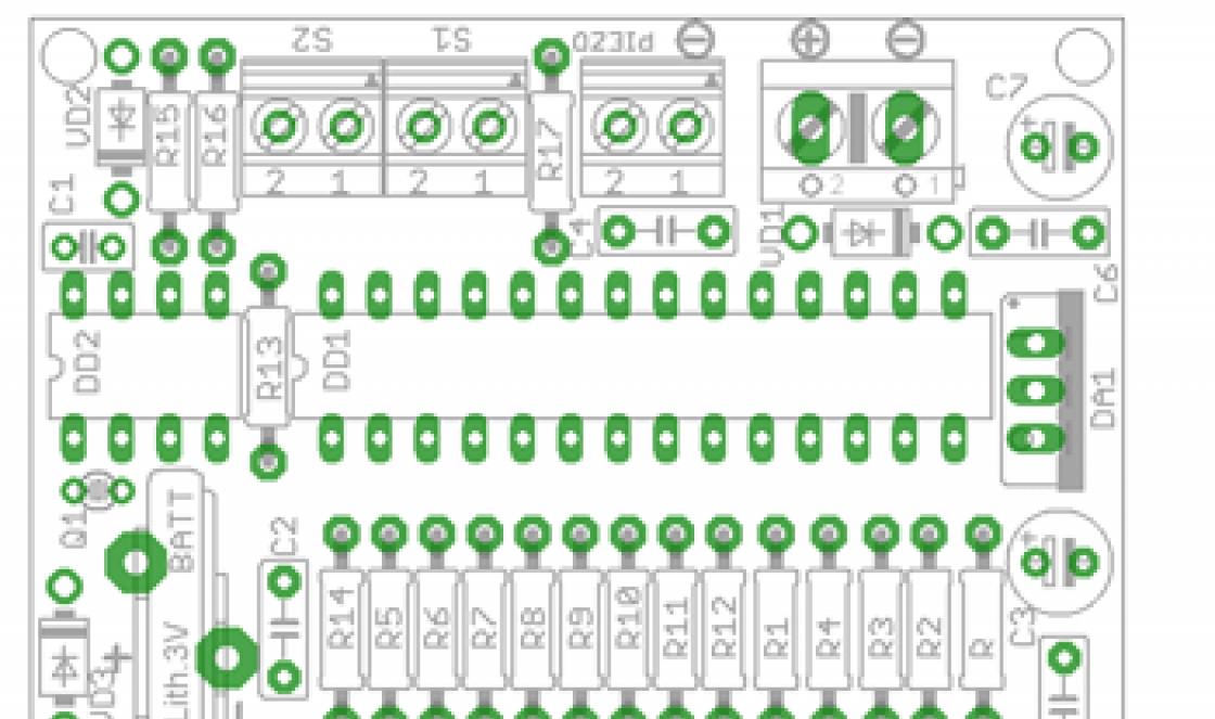
Electrical circuit diagram of the universal oscilloscope S1-101 and its electronic components. Specifications oscilloscope S1-101 and him appearance, photo. Schematic diagram oscilloscope S1-101 is shown in the figures below.
Miniature universal oscilloscope S 1-101 is designed to study the shape of periodic electrical signals by visual observation and measurement of amplitudes in the range from 0.01 V to 300 V and time intervals from 0.3 * 10-6 s to 0.4 s, frequency range from 0 to 5 MHz.
In terms of accuracy of signal reproduction, measurement of time and amplitude values, the S 1-101 oscilloscope belongs to class III GOST 22737-77 Electron-ray oscilloscopes.

The S1-101 oscilloscope can be used in the development, configuration and adjustment of electronic circuits, for testing and repairing instrumentation and various automation devices, both in laboratory and field conditions, in especially hard-to-reach places when setting up and testing computing devices.
terms of Use
- operating ambient temperature from minus 30 °C to +50 °C with power supply I22.087.457 - from minus 20 °C to +50 °C.
- relative air humidity up to 98% at temperatures up to +35° with power supply I22.087.457 - up to 80% at temperatures +35 "C.
The device operates normally after exposure (in the storage box) to shock loads:
- repeated action with acceleration up to 147 m/s2, pulse duration from 5 ms to 10 ms;
- single action with acceleration up to 735 m/s2 and duration from 1 ms to 10 ms;
The device is resistant to cyclic changes in ambient temperature from minus 50 °C to +65 °C; with power supply I22.087.457 - from minus 50 °C to +60 °C.
Technical features
- range of deviation coefficients: 0.005 - 5 V/div;
- sweep factor range: 0.1*10-6 - 0.2 s/div;
- basic measurement error: deviation coefficients ± 5%, sweep coefficients ± 4%;
- beam width less than 0.6 mm;
- screen working area 40 x 30 mm;
- universal power supply 220, 110, 27, and 12 V;
- plastic case;
- operating conditions: temperature from -30 to +50 C, low pressure from 450 mm Hg. Art., rel. air humidity up to 98%;
- Max. input voltage: 300 V;
- Communication with computer: no;
- Power consumption: 18 VA;
- Overall dimensions: 281 x 159 x 71 mm;
- Weight: 1.5 kg;
- Delivery set: 3 probes, 2 of them with a 1:10 divider.
Schematic diagram


Universal oscilloscope S1-101 Amplifier U Electrical circuit diagram I22.035.377 E3.

Universal oscilloscope S1-101 Scan generator and converter. Schematic diagram I23.263.035 E3 Sheet 1.

POWER SUPPLY Electrical circuit diagram I22.087.457 E3.

AUTOMATION DEVICE Electrical circuit diagram I22.070.145 E3.

POWER SUPPLY Electrical circuit diagram I22.087.459 E3.

DIVIDER Electrical circuit diagram I22.727.095 E3.

RECTIFIER Electrical circuit diagram I23.215.184 E3.

RECTIFIER Electrical circuit diagram I23.215.185 E3.

RECTIFIER - Oscilloscope circuit S1-101 I23.215.I86 E3.
RECTIFIER Electrical circuit diagram I23.215.187 E3.

FILTER Electrical circuit diagram I23.290.015 E3.

The O signs indicate automatic control points.
Sweep switch. Electrical circuit diagram I23.602.025 E3.
Electrical data of winding products
Transformer I24.700.009.

The no-load current should not exceed at a network voltage of 110 V - 0.005 A, at a network voltage of 220 V - 0.004 A. The current at rated load should not exceed at a network voltage of 110 V - 0.14 A, at a network voltage of 220 V - 0.07 A .
The current of winding II in the oscilloscope is no more than 1.1 A. Magnetic core YYu7.778.018-0.1.
Transformer I24.730.272.

Cores M20OO NM1-17 K28X16X9-1 (2 pieces).
Transformer I24.730.271.

Core M2000 NM1-P K16X10X4.5-1.