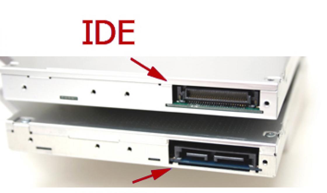
Hello to all blog readers. In this article we will talk about how to restore system performance. Often users have the problem of a very slow computer, especially when recording and at reading disks, or simply unreasonable “brakes” of the system during operation or loading. Why the system freezes read
There can be a great many reasons for this, today I propose to consider a fairly common one - this is an incorrect operating mode CD/DVD - ROM or hard drives, i.e. let's talk about PIO and DMA.Read how to check your hard drive for errors and fix them.
What is the essence and difference between PIO and DMA.
PIO and DMA- these are two modes of operation of hard drives, in the general case of any drive.
PIO (Programmable Input/Output)- already outdated mode, for it to work it needs
engageCPU, which leads to a significant loss of performance.
DMA (Direct MemoryAccess)- a modern method that bypasses the processor and
appeals directly To random access memory, this allows significantly increase productivity and get rid of annoying “brakes”.
DMA mode in various variants has long been used in operating rooms. Windows systems 7, 8, and also at 10, however in Windows XP, there is often a situation in which DMA automatically switches to PIO and it will not be possible to bring it back using conventional methods. What causes this situation?
Implemented in Windows XP mechanism error control, if when reading from hard drive or another drive, errors occur too often, the system automatically switches to a slower mode, where their percentage is lower. However, Windows XP can put a normally operating device into this mode.
How to fix errors
Windows read
And so, let’s check the operating modes of all drives so that the system does not slow down..
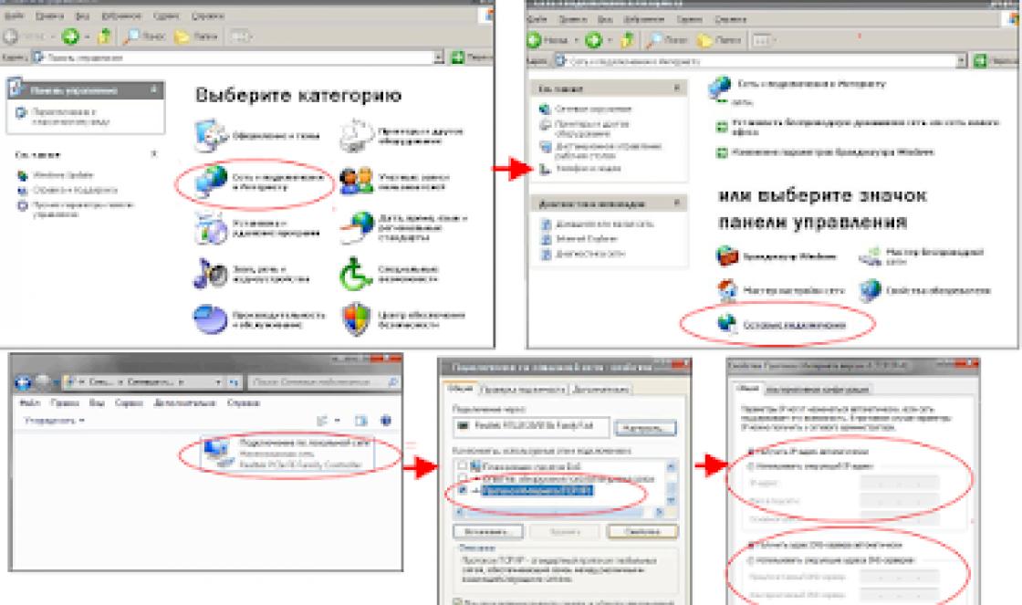
1 . Launch the console "Computer Management"– right click on "My computer"

in the drop-down menu select the item "Device Manager", or through
Control Panel. Or Start - Run - devmgmt.msc
2. Select " Device Manager", select IDE ATA/ATAPI controllers,

Several lines with controllers will open - we are interested in :
Primary and Secondary channels IDE→ we go one by one to properties these channels (right click on the channel, line “ Properties"), to the bookmark " Extra options",
There are two groups here "Device 0" and "Device 1", each has lines
"Transfer Mode"– it must be selected "DMA if available", then the line "Current transmission mode", there must be something like "Ultra DMA mode: 4,

if “PIO mode” is set here, then this is ours case and we will fix it.
If everywhere the mode is worth it ultra DMA, then everything is fine with you and there is no need to continue further actions.
3. First, let's try to fix it manually - in each line “Transfer mode” set to “DMA, if available”, click "OK" and restart the computer. After turning on again
we look at the operating modes of the channels, if DMA is installed everywhere, then everything is in order, if there is PIO left, then we continue further.
4. Find again Primary and Secondary IDE Channels and delete them (right click on each channel, select from the list "Delete"). Don't be afraid, everything will work fine.
Restart your computer again – Windows XP will find controllers and switches them to fast operating mode, i.e. in DMA. Check the result, there should be a mode everywhere DMA.
5. If all of the above did not help and you again see “ PIO mode", then it will be necessary rearrange drivers for the motherboard - reboot
and check the result again.
6. Well, the last point, if after all the suffering the regime PIO didn’t disappear, then you’ll have to edit it in registry I would like to note - perform any operations with
the registry very carefully and carefully; any incorrect action can lead to complete inoperability of your system. It is best to make a copy of the registry in advance.
Read how to configure Windows XP using the registry
First, try disabling the error control system.
To do this, in the registry branch:
HKEY_LOCAL_MACHINE\SYSTEM\CurrentControlSet\Services\Cdfs\,
create a key ErrorControl and set its value to 0.

After that, reboot and follow the step №4.

you can manually set the mode DMA.
There are several folders here - 0000, 0001, 0002.
0000 – responsible for the controller itself;
0001 – responsible for Secondary IDE Chanell;
0002 – responsible for Primary IDE Chanell;
Open the folder for the channel we need. It contains
several keys, first select:
MasteDeviceTimingModeAllowed
SlaveDeviceTimingModeAllowed
and set the value equal to 0хffffffff.
After this, set the value of the following keys:
MasterDeviceTimingMode
SlaveDeviceTimingMode
according to the following data, depending on
supported UDMA modes:
UDMA Mode 2 – 0×2010
UDMA Mode 4 – 0×8010
UDMA Mode 5 – 0×10010
UDMA Mode 6 – 0xffff
After that, reboot and check the result - everything should work fine.
How to speed up and restore Windows 10 performance, read
What is the information transfer speed in computers, read
I hope this article will help you set the modes correctly PIO and DMA and improve overall system performance.
The “original” ATA interface is intended exclusively for connecting an HDD; it does not support such features as the ATAPI interface for connecting IDE devices that are different from the HDD, i.e. transmission mode blockmode or LBA (short for logical block addressing).
After some time, the ATA standard no longer met the growing needs, because newly released HDDs required significantly higher data transfer speeds, as well as new capabilities. Thus, the ATA-2 interface was born, soon also standardized by ANSI. While maintaining intercompatibility with the ATA standard, ATA-2 has several additional features:
- Faster PIO Modes. Added support for PIOmodes 3 and 4;
- Faster DMA Modes. Multiword DMAmodes1 and 2 supported;
- Block Transfer. Commands have been included that allow transfer in blocktransfer mode, in order to improve performance;
- Logical Block Addressing (abbr.. LBA). ATA-2 requires HDD support for the LBA transfer protocol. Of course, to use this protocol, it must also be supported by the BIOS;
- Improved IdentifyDrive command. The interface has increased the amount of information regarding the characteristics provided by the HDD upon system requests.
Everything would be great, but manufacturing companies, in their desire to get a larger piece of the market, began to come up with beautiful names, calling the interfaces of their HDDs with them. After all, the FastATA, FastATA-2, and EnhancedIDE interfaces are essentially based on the ATA-2 standard, being nothing more than beautiful marketing terms. The differences between them are only what part of the standard and how they support.
The biggest confusion comes from the names FastATA and FastATA-2, which belong to smart heads from Seagate and Quantum, respectively. It would be logical to assume that FastATA is a kind of improvement of the ATA standard, while FastATA-2 is based on the ATA-2 standard. Unfortunately, it's not that simple. In reality, FastATA-2 is just another name for the ATA-2 standard. In turn, all the differences between FastATA and it come down only to the fact that the fastest modes are supported here, namely: PIO mode4 and DMA mode2. Both companies, at the same time, attack Western Digital and the EIDE standard it developed for causing even more confusion. EIDE also has its shortcomings, however, more on them later.
In an attempt to further develop the ATA interface, a draft ATA-3 standard was developed, the main focus of which was on improving reliability indicators:
- ATA-3 contains features that increase the reliability of data transfer through the use of high-speed modes, which is a serious problem because... the IDE/ATA cable has remained unchanged since the birth of the standard;
- ATA-3 includes SMART technology.
ATA-3 was not approved as an ANSI standard primarily because it did not use new data transfer modes, despite the fact that SMART technology is now quite widely used by HDD manufacturers.
The next stage in the development of the IDE/ATA interface is the UltraATA standard (also known as UltraDMA or ATA-33, or DMA-33, or ATA-3(!)). UltraATA, in fact, is a standard for using the fastest DMA mode - mode3, which provides a data transfer speed of 33.3 MB/sec. In order to ensure reliable data transfer over the old cable model, special error control and correction schemes are used. Backward compatibility with previous standards: ATA and ATA-2, however, is preserved. Thus, if you bought a HDD with an UltraATA interface and suddenly discovered that it is not supported by your system board, don’t be upset - the drive will still work, although somewhat slower.
Finally, the latest achievement in this area is the UltraATA/66 interface, which was developed by Quantum. The interface allows data transfer at a speed of 66MB/sec.
During the first development of the IDE/ATA interface, the only device that needed this interface was the HDD, because... the nascent CD-ROM drives and streamers were equipped with their own interface (you probably remember the days when connecting a CD-ROM was done using an interface on the sound card). It soon became clear, however, that using a fast and simple IDE/ATA interface to connect all possible devices would bring significant benefits, incl. due to versatility. Unfortunately, the IDE/ATA interface command system was designed exclusively for HDDs, so you cannot simply connect, for example, a CD-ROM to the IDE channel - it simply will not work. Accordingly, it was necessary to develop a new protocol - ATAPI (short for ATA Packet Interface). The protocol allows most other devices to connect using a standard IDE cable and “feel” like an IDE/ATA HDD. The ATAPI protocol is actually much more complex than ATA, because... Data transfer here occurs using the DMA and PIO modes, but the implementation of support for these modes significantly depends on the characteristics of the connected device. The very name packet (from English packet) was received by the protocol due to the fact that the device literally has to transmit commands in groups or packets. From the point of view of the average user, however, the most important thing is that there is no difference between IDE/ATA HDD, ATAPI CD-ROM, and ZIP drive. Today's BIOSes even support booting from ATAPI devices.
Now, as promised, we move on to EIDE. This term was introduced by WesternDigital. EIDE is widely used and almost equally widely criticized, which in our opinion is deserved. The main reason for severe criticism is the fact that, in fact, EIDE is not a standard at all, but a purely marketing term, and the content of this term is constantly changing. So, at first EIDE included support for PIO modes up to mode3, then support for mode4 was added. A significant drawback of EIDE as a standard is the inclusion of completely diverse things in its specification. See for yourself at this moment EIDE includes:
- ATA-2. Completely, incl. the highest speed modes;
- ATAPI. Entirely;
- Dual IDE/ATA Host Adapters. The EIDE standard includes support for 2 IDE/ATA hosts, so you can use up to 4 IDE/ATA/ATAPI devices in parallel.
Let’s now look at what the phrase “HDD with EIDE interface” means. Since it makes no sense to support ATAPI, and it won’t be able to support 2 IDE channels, it all comes down to the modest: “HDD with ATA-2 interface.” The idea, in principle, was not bad - to create a standard that covers the chipset, BIOS and hard drive. However, since most of EIDE as a standard relates directly to the chipset and BIOS, there is confusion between EnhancedIDE and EnhancedBIOS that emerged around the same time (i.e., a BIOS that supports IDE/ATA for HDDs with a capacity of more than 504MB). It would be quite logical to assume that to use a HDD with a capacity of more than 504 MB, an EIDE interface is required, however, as you already understood, only EnhancedBIOS is needed. Moreover, manufacturers of cards with EnhancedBIOS advertised them as "enhanced IDE cards". Fortunately, these problems are now a thing of the past, as is the 540MV barrier.
In order to somehow systematize the information, all the main (official and unofficial) IDE interface standards that were described above are presented in table form.
|
Standard |
Interface |
DMA modes |
PIO modes |
Differences from IDE/ATA |
|
Singleword 0-2; multiword 0 |
||||
|
Singleword 0-2; multiword 0-2 |
Support LBA, block transfer mode, improved identify drive command |
|||
|
Marketing term |
Singleword 0-2; multiword 0, 1 |
Similar to ATA-2 |
||
|
Marketing term |
Singleword 0-2; multiword 0-2 |
Similar to ATA-2 |
||
|
Informal |
Singleword 0-2; multiword 0-2 |
Similar to ATA-2, with added support for transfer reliability at high speeds, SMART technology is used |
||
|
Informal |
Singleword 0-2; multiword 0-3 (DMA-33/66) |
Similar to ATA-3 |
||
|
Singleword 0-2; multiword 0-2 |
Similar to ATA-2, added support for devices other than HDD |
|||
|
Marketing term |
Singleword 0-2; multiword 0-2 |
Similar to ATA-2 +ATAPI, supports 2 host adapters |
We smoothly move on to an equally interesting topic. In total, there are 2 parameters that characterize the data transfer speed when using a HDD with an IDE/ATA interface. The first of them is the internal transfer rate, which characterizes the speed of data transfer between the internal HDD buffer and magnetic media. It is determined by the rotation speed, recording density, etc. Those. parameters that depend not on the type of interface, but on the design of the carrier. The second indicator is the external data transfer speed, i.e. data transfer speed over the IDE channel, which completely depends on the data transfer mode. At the very beginning of the use of IDE/ATA drives, the operating speed of the entire disk subsystem depended on the internal data transfer speed, which was significantly lower than the external one. Today, thanks to an increase in recording density (this allows more data to be captured per disk revolution) and an increase in rotation speed, the external transmission speed plays a dominant role. In this regard, a question arises regarding mode numbers and the difference between PIO and DMA.
Initially, a common method of transferring data via the IDE/ATA interface was a protocol called Programmed I/O (abbr. PIO). There are 5 PIO modes in total, which differ in maximum burst transfer rates. These modes are called PIO modes.
Of course, this refers to the external data transfer speed, determined by the speed of the interface, and not the HDD. It should also be taken into account, although this is hardly relevant today, that PIO modes 3 and 4 need to use the PCI or VLB bus, because The ISA bus is not capable of providing data transfer speeds greater than 10 MB/sec.
Until the advent of DMA-33 mode, the maximum data transfer speed of PIO and DMA was identical. The main disadvantage of PIO modes is that data transfer is controlled by the processor - this significantly increases its load. On the other hand, these modes do not require special drivers and are perfect for single-tasking operating systems. Unfortunately, this is most likely an endangered species...
Direct Memory Access (abbreviated from DMA) - direct memory access - refers to the collective name of protocols that allow peripheral device transfer data to system memory directly without CPU involvement. Modern hard drives use this feature in combination with the ability, by intercepting bus control, to independently manage data transfer (the so-called bus mastering). Existing DMA modes (so-called DMAmodes) are shown in the table. It should be noted that singleword modes are no longer used today; they are provided for comparison purposes only.
|
Maximum transfer speed (MV/sec) |
Standards supported: |
|
|
ATA-2, FastATA, FastATA-2, ATA-3, UltraATA, EIDE |
||
|
ATA-2, FastATA-2, ATA-3, UltraATA, EIDE |
||
|
Multiword 3 (DMA-33) |
UltraATA (ATA/66) |
Another interesting point regarding the operation of the IDE/ATA interface is 32-bit access to the HDD. As you already know, the IDE/ATA interface has always been and remains 16-bit to this day. In this case, it would be appropriate to ask why, when you turn off the drivers for 32-bit HDD access, Windows speed does this disk fail? First of all, because Windows work, in principle, is far from perfect. Secondly, the PCI bus, on which IDE host controllers are currently located, is 32-bit. Therefore, a 16-bit transfer on this bus is a waste of bandwidth. Under normal conditions, the host controller forms a 32-bit packet from 2 16-bit packets, sending it further via the PCI bus.
Previously, we came across such a term as blocktransfer mode. Nothing complicated here. In fact, this term simply refers to a mode that allows a certain number of read/write commands to be transmitted during a single interrupt. Modern IDE/ATA HDDs allow you to transfer 16->32 sectors per interrupt. Since interrupts are generated less frequently, processor load is reduced, and the percentage of commands in the total amount of data transferred is also reduced.
Each IDE channel allows you to connect one or two devices to it. Modern computers, as a rule, are distinguished by the installation of two IDE channels (in accordance with the EIDE specification), despite the fact that it is theoretically possible to install up to four (!), which allows the connection of eight IDE devices. All IDE channels are equal. The table shows the use of system resources by various channels.
|
Channel |
I/O Addresses |
Support, possible problems problems arising when using |
|
|
1F0-1F7h, as well as 3F6-3F7h |
Used in any computers equipped with an IDE/ATA interface |
||
|
170-177h, as well as 376-377h |
Widely distributed, present in almost all modern PCs. |
||
|
1E8-1Efh, as well as 3EE-3Efh |
Rarely used. There may be certain problems with the software |
||
|
168-16Fh, as well as 36E-36Fh |
Used extremely rarely. Problems with the software are very likely |
Resources that are used by the third and fourth channels usually conflict with other devices (for example, IRQ 12 is used by a PS/2 mouse, IRQ 10 is traditionally occupied by a network card).
As already noted, each IDE/ATA interface channel supports the connection of 2 devices, namely: master and slave. The configuration is usually set by a jumper located on the rear wall of the device. In addition to these two positions, there is often also a third one - cableselect. What happens if the jumper is placed in this position? It turns out that for the devices to function in the cableselect jumper position, a special Y-shaped cable is required, in which the central connector is connected directly to system board. With this type of cable, the extreme connectors are unequal - a device that is connected to one connector is automatically defined as a master, and to the other, respectively, as a slave (similar to A and B flops). The jumpers on both devices must be in the cableselect position. The main problem with this configuration is that it is exotic, despite the fact that it is de jure considered standard, which means it is not supported by everyone. This makes the Y-shaped cable very difficult to obtain.
Assuming that, despite the exotic nature, you will still use the described configuration of IDE/ATA devices, remember the following:
- At any time, each channel can process only one request and only to one device. That is, the next request, even to another device, will have to wait for the current one to complete. Different channels can operate independently. Therefore, you should not connect 2 devices that are actively used (for example, two HDDs) to one channel. The best option would be to connect each IDE device to a separate channel (this is perhaps the main disadvantage compared to SCSI).
- Almost all chipsets today support the ability to use different data transfer modes for devices connected to the same channel. However, you should not abuse this. It is recommended to separate two devices that differ significantly in speed on different channels.
- It is also recommended not to connect the HDD and ATAPI device (for example, CD-ROM) to the same channel. As stated above, the ATAPI protocol uses a different command system, and, moreover, even the fastest ATAPI devices are much slower than the HDD, which can significantly slow down the latter.
The above, of course, cannot be considered an axiom - these are only recommendations that are based on common sense and the experience of experts. In addition, common sense and experience suggest that four IDE devices on a working board can work in any combination and with minimal effort on the part of the user, if compatibility requirements are met. This is the main advantage of IDE over SCSI.
Other identical option names: IDE Channel 0 Master, Primary Master.

There are several options in the BIOS designed to configure settings for hard drives and other internal storage devices (drives). The Primary IDE Master option is one of the most commonly used of its kind.
As a rule, before the advent of the SATA interface, most motherboards personal computers only supported IDE interface drives. Typically, the user could install no more than 4 drives - hard drives or CD/DVD drives. Two of them can be located on the primary IDE channel (Primary), and the other two on the secondary channel (Secondary). In each of these two pairs of drives, one drive is the master (Master), and the second is the slave (Slave). Thus, in the BIOS, as a rule, there are four options for configuring drives:
- Primary IDE Master
- Primary IDE Slave
- Secondary IDE Master
- Secondary IDE Slave
Each IDE channel is a connector to which you connect an IDE data cable, which in turn has three connectors. One of them is designed to connect to the IDE connector on motherboard, the other two are for connecting storage devices. The choice of which category the drive will belong to - the Master or Slave category is determined solely by the installation of jumpers on the drives, which must be carried out in accordance with the instructions supplied with the drive.
In the parameter you can see a number of subordinate options that can determine the type of drive, its characteristics, capacity and some operating parameters.
The most important of these options is the Type option. As a rule, it can take the following values:
- Auto – drive type is detected automatically
- User – the user can set the drive type manually
- CDROM – the drive is a CD/DVD drive
- ZIP drive is an Iomega ZIP type device
- LS-120 – the drive is a device of the LS-120 type
- None this device not used
Also, in this option, you can sometimes select a predefined drive type, designated by a number, for example, from 0 to 50.
If the user selects the User value, then he will have to specify the characteristics of the hard drive himself, such as the number of heads, cylinders and sectors.
The following additional options are also often found:
- LBA Mode
- (Block recording mode)
- Programmed I/O Modes
Which value should I choose?
As a rule, after connecting the drive and booting the computer, the BIOS automatically selects the Type option value equal to Auto for it. This means that the BIOS automatically detects all drive parameter values, and manual setting it is not required.
The vast majority of IDE drives support automatic configuration. The only exceptions may be very old drives, rarely found in ancient computers, which may require manual setting of the number of heads, cylinders and sectors.
The LBA Mode option requires some explanation. This option is intended to enable the addressing mode used in hard drives larger than 504 MB. If you are using a smaller hard drive, you should disable this option. For other parameters, it is best to leave the default values.
And with its appearance it received the name PATA(Parallel ATA).
Story
ATA (IDE) cables: 40-wire on top, 80-wire with cable exit on bottom
Adapter from IDE to 2.5" IDE ( hard drives laptops)
The preliminary name of the interface was PC/AT Attachment(“PC/AT Connection”), since it was intended to connect to the 16-bit ISA bus, then known as AT bus. In the final version the title was changed to AT Attachment to avoid problems with trademarks.
The original version of the standard was developed in 1986 by Western Digital and, for marketing reasons, was called IDE(English: Integrated Drive Electronics - “electronics built into the drive”). It emphasized an important innovation: the drive controller is located in the drive itself, and not in the form of a separate expansion card, as in the previous ST-506 standard and the then existing SCSI and ST-412 interfaces. This made it possible to improve the characteristics of drives (due to the shorter distance to the controller), simplify their management (since the IDE channel controller was abstracted from the details of the drive operation) and reduce the cost of production (the drive controller could be designed only for “its” drive, and not for all possible drives). ; the channel controller generally became standard). It should be noted that the IDE channel controller is more correctly called host adapter, since it moved from directly controlling the drive to exchanging data with it via a protocol.
The ATA standard defines the interface between the controller and the drive, as well as the commands transmitted over it.
The interface has 8 registers occupying 8 addresses in the I/O space. The data bus width is 16 bits. The number of channels present in the system can be more than 2. The main thing is that the addresses of the channels do not overlap with the addresses of other I/O devices. Each channel can connect 2 devices (master and slave), but only one device can operate at a time.
The CHS addressing principle is in its name. First, the head block is installed by the positioner on the required track (Cylinder), after which the required head (Head) is selected, and then information is read from the required sector (Sector).
Standard EIDE(English Enhanced IDE - “extended IDE”), which appeared after IDE, allowed the use of drives with a capacity exceeding 528 MB (504 MiB), up to 8.4 GB. Although these abbreviations originated as trade names rather than official names for the standard, the terms IDE And EIDE often used instead of the term ATA. Since the introduction of the standard in 2003 Serial ATA(“serial ATA”) traditional ATA began to be called Parallel ATA, referring to the method of transmitting data over a parallel 40- or 80-core cable.
At first, this interface was used with hard drives, but then the standard was expanded to work with other devices, mainly using removable media. Such devices include CD-ROM and DVD-ROM drives, tape drives, as well as high-capacity floppy disks such as ZIP and floptic (use laser-guided magnetic heads) disks (LS-120/240). In addition, from the FreeBSD kernel configuration file we can conclude that even floppy disk drives (floppy disks) were connected to the ATAPI bus. This extended standard is called Advanced Technology Attachment Packet Interface(ATAPI), and therefore the full name of the standard looks like ATA/ATAPI. ATAPI is almost completely identical to SCSI at the command level and, in fact, is “SCSI over ATA cable.”
Initially, interfaces for connecting CD-ROM drives were not standardized and were proprietary developments of drive manufacturers. As a result for CD-ROM connections it was necessary to install a separate expansion card specific to a particular manufacturer, for example, for Panasonic (there were at least 5 specific interface options designed to connect a CD-ROM). Some options sound cards, for example, Sound Blaster, were equipped with just such ports (often a CD-ROM drive and sound card supplied as a multimedia kit). The advent of ATAPI made it possible to standardize all this peripherals and make it possible to connect them to any controller to which a hard drive can be connected.
Another important stage in the development of ATA was the transition from PIO (Programmed input/output) to DMA (Direct memory access). When using PIO, reading data from the disk was controlled by the computer's central processor, which led to increased load on the processor and slower operation in general. Because of this, computers that used the ATA interface typically performed disk-related operations more slowly than computers that used SCSI and other interfaces. The introduction of DMA significantly reduced the CPU time spent on disk operations.
In this technology, the drive itself controls the data flow, reading data into or from memory with almost no participation of the processor, which only issues commands to perform one or another action. Wherein HDD issues a DMARQ request signal for a DMA operation to the controller. If the DMA operation is possible, the controller issues a DMACK signal, and the hard drive begins to output data to the 1st register (DATA), from which the controller reads data into memory without the participation of the processor.
DMA operation is possible if the mode is supported simultaneously by the BIOS, controller and operating system, otherwise only PIO mode is possible.
In the further development of the standard (ATA-3), an additional mode UltraDMA 2 (UDMA 33) was introduced.
This mode has the timing characteristics of DMA Mode 2, but data is transmitted on both the rising and falling edges of the DIOR/DIOW signal. This doubles the data transfer speed over the interface. A CRC parity check has also been introduced, which increases the reliability of information transmission.
In the history of ATA development, there were a number of barriers associated with organizing access to data. Most of these barriers have been overcome thanks to modern addressing systems and programming techniques. These include maximum disk size restrictions of 504 MiB, about 8 GiB, about 32 GiB, and 128 GiB. There were other barriers, mainly related to device drivers and the organization of I/O in operating systems that did not comply with ATA standards.
The original ATA specification provided for a 28-bit addressing mode. This allowed 228 (268,435,456) sectors of 512 bytes each to be addressed, giving a maximum capacity of 137 GB (128 GiB). On standard PCs, the BIOS supported up to 7.88 GiB (8.46 GB), allowing a maximum of 1024 cylinders, 256 heads, and 63 sectors. This limitation on the number of CHS (Cylinder-Head-Sector) cylinders/heads/sectors, combined with the IDE standard, resulted in an addressable space limitation of 504 MiB (528 MB). To overcome this limitation, the LBA (Logical Block Address) addressing scheme was introduced, allowing up to 7.88 GiB to be addressed. Over time, this limitation was lifted, which made it possible to address first 32 GiB, and then all 128 GiB, using all 28 bits (in ATA-4) to address the sector. Writing a 28-bit number is organized by writing its parts into the corresponding registers of the drive (from 1 to 8 bits in the 4th register, 9-16 in the 5th, 17-24 in the 6th and 25-28 in the 7th) .
Register addressing is organized using three address lines DA0-DA2. The first register, address 0, is 16-bit and is used to transfer data between the disk and the controller. The remaining registers are 8-bit and are used for control.
The latest ATA specifications call for 48-bit addressing, thus expanding the possible limit to 128 PiB (144 petabytes).
These size restrictions can manifest themselves in the fact that the system thinks that the disk capacity is less than its real value, or even refuses to boot and hangs at the stage of initializing hard drives. In some cases, the problem can be solved by updating the BIOS. To others possible solution is the use of special programs, such as Ontrack DiskManager, which loads its driver into memory before loading operating system. The disadvantage of such solutions is that a non-standard disk partition is used, in which disk partitions are inaccessible if booted, for example, from a regular DOS boot floppy disk. However, many modern operating systems (starting from Windows NT4 SP3) can work with larger disks, even if the computer BIOS does not correctly determine this size.
ATA interface
To connect hard drives with a PATA interface, a 40-wire cable (also called a cable) is usually used. Each cable usually has two or three connectors, one of which connects to the controller connector on the motherboard (in older computers, this controller was located on a separate expansion card), and one or two others connect to the drives. At one point in time, the P-ATA cable transmits 16 bits of data. Sometimes there are IDE cables that allow connecting three drives to one IDE channel, but in this case one of the drives operates in read-only mode.
| Contact | Purpose | Contact | Purpose |
|---|---|---|---|
| 1 | Reset | 2 | Ground |
| 3 | Data 7 | 4 | Data 8 |
| 5 | Data 6 | 6 | Data 9 |
| 7 | Data 5 | 8 | Data 10 |
| 9 | Data 4 | 10 | Data 11 |
| 11 | Data 3 | 12 | Data 12 |
| 13 | Data 2 | 14 | Data 13 |
| 15 | Data 1 | 16 | Data 14 |
| 17 | Data 0 | 18 | Data 15 |
| 19 | Ground | 20 | Key |
| 21 | DDRQ | 22 | Ground |
| 23 | I/O Write | 24 | Ground |
| 25 | I/O Read | 26 | Ground |
| 27 | IOC HRDY | 28 | Cable Select |
| 29 | DDACK | 30 | Ground |
| 31 | IRQ | 32 | No Connect |
| 33 | Addr 1 | 34 | GPIO_DMA66_Detect |
| 35 | Addr 0 | 36 | Addr 2 |
| 37 | Chip Select 1P | 38 | Chip Select 3P |
| 39 | Activity | 40 | Ground |
Option for connecting 4 disk devices
The jumper on the optical drive is set to slave(SL)
Options for setting jumpers on disk devices with an IDE interface
For a long time, the ATA cable contained 40 conductors, but with the introduction of the Ultra DMA/66 (UDMA4) its 80-wire version appeared. All additional conductors are grounding conductors alternating with information conductors. Thus, instead of seven grounding conductors, there are 47 of them. This alternation of conductors reduces the capacitive coupling between them, thereby reducing mutual interference. Capacitive coupling is a problem at high transmission speeds, so this innovation was necessary to ensure proper operation of the specified specification UDMA4 transfer speed of 66 MB/s (megabytes per second). Faster Modes UDMA5 And UDMA6 also require 80-wire cable.
Although the number of conductors has doubled, the number of contacts remains the same, as well as appearance connectors. The internal wiring is, of course, different. Connectors for an 80-wire cable must connect a large number of ground conductors to a small number of ground pins, whereas a 40-wire cable connects the conductors to each of their own pins. 80-wire cables usually have connectors of different colors (blue, gray and black), unlike 40-wire cables, where usually all connectors are the same color (usually black).
The ATA standard has always set the maximum cable length to 45.7 cm (18 inches). This limitation makes it difficult to attach devices in large cases, or connect multiple drives to a single computer, and almost completely eliminates the possibility of using PATA drives as external drives. Although longer cable lengths are widely available, keep in mind that they are not standard. The same can be said about “round” cables, which are also widely used. The ATA standard only describes flat cables with specific impedance and capacitance characteristics. This, of course, does not mean that other cables will not work, but in any case, the use of non-standard cables should be treated with caution.
If two devices are connected to the same loop, one of them is usually called leading(English master), and the other - slave(English slave). Typically, the master device comes before the slave device in the list of drives listed by the computer's BIOS or operating system. In older BIOSes (486 and earlier), drives were often incorrectly designated by letters: "C" for master and "D" for slave.
If there is only one drive on a loop, it should in most cases be configured as a master. Some drives (particularly those made by Western Digital) have a special setting called single(i.e. "one drive per cable"). However, in most cases, the only drive on the cable can also work as a slave (this often occurs when connecting a CD-ROM to a separate channel).
A setting called cable select was described as optional in the ATA-1 specification and has become common since ATA-5 because it eliminates the need to reset drive jumpers for any reconnections. If the drive is set to cable select mode, it is automatically set as master or slave depending on its location on the loop. To be able to determine this location, the loop must be with cable sampling. In such a cable, pin 28 (CSEL) is not connected to one of the connectors (gray, usually middle). The controller grounds this pin. If the drive sees that the contact is grounded (that is, it is logic 0), it is set as a master, otherwise (high impedance state) it is set as a slave.
In the days of 40-wire cables, it was common practice to install cable select by simply cutting conductor 28 between the two connectors that connected to the drives. In this case, the slave drive was at the end of the cable, and the master drive was in the middle. This placement was even standardized in later versions of the specification. When only one device is placed on a cable, this placement results in an unnecessary piece of cable at the end, which is undesirable - both for reasons of convenience and for physical reasons: this piece leads to reflection of the signal, especially at high frequencies.
The 80-wire cables introduced for UDMA4 do not have these disadvantages. Now the master device is always at the end of the loop, so if only one device is connected, you don't end up with this unnecessary piece of cable. Their cable selection is “factory” - made in the connector itself simply by eliminating this contact. Since 80-wire loops required their own connectors in any case, widespread adoption of this did not amount to big problems. The standard also requires the use of connectors of different colors to make them easier to identify by both the manufacturer and assembler. The blue connector is for connecting to the controller, the black connector is for the master device, and the gray connector is for the slave.
The terms “master” and “slave” were borrowed from industrial electronics (where this principle is widely used in the interaction of nodes and devices), but in this case they are incorrect, and therefore are not used in the current version of the ATA standard. It is more correct to call the master and slave disks respectively device 0 (device 0) And device 1 (device 1). There is a common myth that the master disk controls the disks' access to the channel. In fact, the controller (which, in turn, controls the operating system driver) controls disk access and the order of command execution. That is, in fact, both devices are slaves in relation to the controller.
ATA Standard Versions, Baud Rates and Properties
The table below shows the names of the versions of the ATA standard and the modes and transfer rates they support. It should be noted that the transfer rate specified for each standard (for example, 66.7 MB/s for UDMA4, commonly referred to as "Ultra-DMA 66") indicates the maximum speed theoretically possible on the cable. This is simply two bytes multiplied by the actual frequency and assumes that each cycle is used to transfer user data. In practice, the speed is naturally lower.
Congestion on the bus to which the ATA controller is connected can also limit the maximum transfer level. For example, the maximum throughput of a PCI bus operating at 33 MHz and 32 bits is 133 MB/s, and this speed is shared among all devices connected to the bus.
| Standard | Other names | Added transfer modes (MB/s) | Scott Mueller. Upgrading and Repairing PCs = Upgrading and Repairing PCs. - 17th ed. - M.: Williams, 2007. - P. 573-623. - ISBN 0-7897-3404-4.
|---|