A programmer is required to program AVR microcontrollers. The easiest way is to make a programmer for COM or LPT. But I work on a laptop, and now they only install USB ports. So there is a need to get a programmer for the AVR via USB. Now, I would most likely buy this programmer. On ebay, they are inexpensive, probably even cheaper than buying parts, making a board and soldering everything. Although if you look from the other side, an order from ebay will go by mail for at least a month, and you can assemble the avr usb programmer with your own hands, due to its simplicity, in an evening. Moreover, if a novice radio amateur assembles a programmer himself, then in addition to the programmer, he will gain experience, invaluable experience, and this is worth a lot.
This is my second USB programmer for AVR, the first one I made was a USB-asp programmer, but I didn't really like it, as it sometimes fell off my computer, although nothing like this was observed on another computer. I decided to try to assemble another programmer, and my choice fell on the AVR910 programmer. This programmer has a slightly different USB connection scheme, and as it turned out later, everything works very well on my computer. I forgot about the problems I had with my past programmer. The AVR910 programmer described in this article is on this moment my main AVR programmer.
Schematic and firmware used from the project website (http://prottoss.com/projects/AVR910.usb.prog/avr910_usb_programmer.htm). 
The programmer is powered by a USB port. In order not to be required to match the data line levels of the USB port (3.6V), the microcontroller is powered by 3.6V. To get 3.6V from 5V in the USB port, a circuit of two silicon diodes directly connected in series is used. Each diode drops 0.7V, for a total of 1.4V. The diodes must be silicon, the use of Schottky diodes is not allowed, since less than 0.7V falls on them. The outputs of the programming connector are connected through 330 Ohm resistors for level matching. The device works on the AtMega8-16 microcontroller at a clock frequency of 12 MHz. The diagram shows the pin numbers for the microcontroller in a DIP package, although I routed the board under SMD housing, which is called TQFP. The programmer has an indication of writing, reading, power supply. Also, this programmer has an output, on which a meander is always present, with a frequency of 1 MHz. This is a very cool and useful thing for recovering microcontrollers that, due to erroneously programmed Fuse bits, are configured to clock from an external clock source. I have restored microcontrollers in this way several times. You just need to look in the datasheet for a specific AVR microprocessor, to which pin the external clock signal source is connected, and solder the meander source to this pin. Connect the programmer, and reprogram fuse. It's very simple, but sometimes it helps a lot!
The available options for the implementation of printed circuit boards for the AVR910 programmer did not quite suit me, and I traced my version (you can download the project files at the end of the article). 
The protective pattern on the foil fiberglass is applied using laser printer and iron. 
After etching, this beauty turned out. I could not restrain myself and scratched the toner on the tracks between the legs of the microcircuit. I couldn't wait to see if they worked or not. 

For ease of use, I noted the purpose of each output of the AVR910 programmer. To do this, I drew a small plate, which I printed on glossy photo paper and pasted on the programmer board with double-sided tape. 
I put a group blank for a plate for printing on photographic paper 10x15 in size in an archive with all the files for this entry. You can download it at the end of this article.
The firmware for the programmer can be downloaded from the link at the end of the article.
Fuse bits are installed according to the figure below: 
How to program the AtMega8 microcontroller for the AVR910 programmer can be seen in my video:
I could not find a case for the AVR910 programmer, I wanted the programmer to remain small in size, and initially I used a bare, not insulated board. But then I bought a wide transparent heat shrink and put the programmer in it. What happened in the end you can see in the photo. In my opinion, it is quite interesting and even cute. 

With heat shrink everything seems easy, but I had a hard time making holes for the pins. If you pierce the holes with an awl, then during shrinkage, the heat shrink tubing breaks starting from these holes. I even ruined a few blanks, but at the end of the experiments everything worked out for me. As a result, I did not pierce the holes, but melted them with a hot soldering iron with a sting with a needle. Along the edges of the board, I soldered the ends of the heat shrink tube. They are soldered very simply - both ends of the tube heat up, then quickly, until they have time to cool down, they are clamped and held clamped until they cool completely. It turns out a fairly strong joint. I clamped it with a medical clamp, the heat shrink even left traces of notches on his lips.
When the AVR910 programmer is connected to the computer for the first time, a new AVR910 device will appear in the system. Now you need to install the drivers and you can work.
I worked with this programmer on 32 bit Windows systems XP and Windows 7. Everything works very well and there are no problems. I had problems when I tried to install drivers for 64-bit Windows 7. The fact is that this driver does not have digital signature Microsoft and 64 bit Windows 7, being more secure, will block all unsigned drivers. This blocking can be disabled, but it's not exactly easy….. So be aware.
I upload the firmware to the microcontroller using the AvrOsp2 program. It is very simple, does not require installation, is free, supports the AVR910 programmer and a huge number of AVR microcontrollers, works well and has a very convenient menu for working with FUSE bits. In general, a cool program, I really like it, I recommend it! In the video below, I showed the process of installing drivers for the AVR910, how to set up and use the AvrOsp2 program.
In my version of the programmer, I did not install a 22 uF output electrolytic capacitor, which is installed on the opposite side of the tracks and soldered into the holes that are located near the USB connector. It may be necessary to install an additional 10-50uF electrolytic capacitor in parallel with the soldered 0.1uF ceramic capacitor, near the green PWR LED. Below in the picture, by hand, the connection points are shown. 
The programmer requires a microcontroller capable of operating up to 16 MHz. AVR AtMega8 is available in two series operating up to 8 MHz (L series), they are not suitable for us, since the project runs on 12 MHz quartz. There is also a regular version that works up to a frequency of 16 MHz. This is what we need. Below is a piece of the AVR AtMega8 datasheet, in which the versions of microcontrollers that will not work in this programmer are crossed out, and the versions of microcontrollers that will work in this project are highlighted with a green frame. 
We will learn what an ISP interface is, we will deal with an inexpensive and convenient USB ISP programmer. Consider the circuit diagrams of the simplest programmers for AVR microcontrollers using the COM and LPT ports of a computer. This information is quite enough to flash most AVR microcontroller models not only in Linux, but also in other operating systems.
ISP In-System Programming Interface
In order to write a program to the AVR microcontroller, you will need a programmer.
programmer- it's small electronic circuit, which allows you to connect the microcontroller to one of the computer ports (COM, LPT, USB) for subsequent reading and writing firmware (programming).
There are quite a few different designs of programmers for AVR microcontrollers that connect to different ports on a computer.
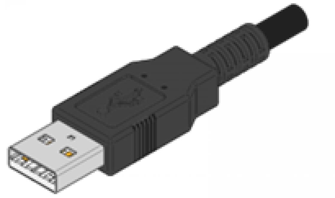
The most reliable and convenient option is a programmer that connects to a USB port, since in new desktop computers and laptops no longer install COM and LPT ports.
In finished devices, the programmer is connected to the microcontroller via an interface ISP(In System Programming) - an interface for intra-system programming. The ISP interface consists of several conductors through which the clock signal and data are received to connect the programmer with the microcontroller.
As a rule, the ISP interface is placed on boards in the form of ten or six pins, to which the programmer is connected via a suitable connector via a cable.
Rice. 4. ISP interface on the board.
Pin assignment in ISP interface:
- VCC - plus power supply, usually + 5V;
- GND - minus power supply, ground (Ground);
- MOSI - data input (Master Out Slave In);
- MISO - data output (Master In Slave Out);
- SCK - clock signal (Serial Clock);
- RST - to send a reset signal (Reset).
For in-circuit programming of the microcontroller, only 4 pins are enough, since the microcontroller can be powered from the circuit itself where it is installed.
How to connect the programmer to the AVR microcontroller chip if it is not soldered into the circuit? - very simple, using the same pins of the ISP interface, if necessary, powering the microcontroller from a power source.
Programmer USB ISP ASP
To work with AVR chips, I purchased an inexpensive USB ISP programmer for about $10. Such a device is now on sale in many domestic and foreign online stores, so there should be no problems with the purchase.

Rice. 5. USB ISP - programmer with a cable for in-circuit AVR programming ATMEL microcontrollers.
This programmer is safe to use, has a small size and is supported by most programs for flashing AVR microcontrollers. The USB ISP runs under Linux, Mac OS X and Windows operating systems. For Linux, you do not need to install any drivers, after connecting the programmer to the USB port, the device will be immediately detected and ready for use.
Below is the pinout of the USB ISP programmer connectors - it will come in handy later when connecting to the microcontroller.

Rice. 6. The location of the pins on the USB ISP connector (pinout).

Rice. 7. The location of the contacts in the sockets of the connector connected to the USB ISP programmer.
What to do if it is not possible to buy a USB ISP programmer?- you can program microcontrollers using simple home-made programmers that connect to a COM or LPT port, but it is better to make a USB ISP yourself while programming the microcontroller chip for it once with a simple home-made programmer through a COM or LPT port.

Rice. eight. circuit diagram homemade programmer USB ASP ISP.
Detailed information on the manufacture of USB ASP, as well as printed circuit boards, drivers and firmware for the microcontroller can be found on the official website: http://www.fischl.de/usbasp/
In addition, there are a lot of resources on the Internet for this free programmer, there are many ready-made PCB layouts, including in the SprintLayout program, so we will not dwell on this in detail in this article.
Programmer using COM port
This programmer is also called the "Gromov programmer", in honor of the one who came up with this scheme, the creator of the Algorithm Builder program (a graphical environment for programming AVR under Windows using algorithmic language) - G.L. Gromov.
This programmer allows you to program AVR chips using COM port computer - RS232 interface. To assemble such a programmer, you will need a minimum of parts - 3 diodes, 7 resistors, a DB-9 or DB-25 connector (depending on which mating connector is installed in your computer) and an ISP connector for connecting to a microcontroller (or just a few conductors to chip). Diodes in the circuit can be used any low-power.

Rice. 9. Schematic diagram of the programmer AVR microcontrollers through the COM port of the computer.
For completeness of information, below is the pinout of the RS-232 ports for the DB-9 and DB-25 options.

Rice. 10. RS232 - COM Port, DB-9 pinout.

Rice. 11. RS232 COM Port DB-25 - pinout on connectors.
Programmer using LPT port
As we know, the LPT port of a computer is designed to connect a local printer (Local Printer Port), but nevertheless it is often used to connect various devices and homemade. In this case, we can use it to program AVR microcontrollers by assembling a very simple circuit for this purpose, which is shown below.
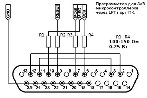
Rice. 12. Schematic diagram of the programmer for AVR microcontrollers using the LPT port of the computer.
As you can see, the circuit is even simpler than in option c, here we only need 4 low-power resistors and a connector (male, with pins) for connecting to the LPT port of the computer.

Rice. 13. Location of pins for LPT-port connectors.
All parts and connections can be placed in the housing of the LPT connector, and to connect to the microcontroller, bring out a cable with a connector for the ISP interface or just the necessary conductors for connecting to the microchip.
Software and Notes
Having connected a COM or LPT programmer to the microcontroller, you must remember to supply power to the microchip itself. You can use batteries or a power supply with a stabilizer as a power source for the microcontroller, this will be the safest for both the computer port and the chip. We have already discussed how to use it.
Under Linux there is a very powerful program that can work with USB ASP, COM and LPT programmers - this is a program AVRDUDE, which will be discussed in the following sections.
To flash AVR chips under Windows using these COM and LPT programmers, you need the UniProf program from Nikolaev, which is a universal programmer for AVR (avr.nikolaew.org).
ATTENTION! Be extremely careful and careful when assembling and using programmers using the computer's COM or LPT port, a simple mistake can easily set those ports on fire. For the normal operation of such programmers, you should try to use the shortest possible conductors from the connector to the programmer circuit and the microcontroller. It is desirable that the computer microprocessor has a frequency of no more than 1-2 GHz, and it is desirable to use Win2000 or WinXP as an OS for programming chips.
It is also important to know that USB-RS232 adapters (USB-COM Port) most likely will not work with the Gromov programmer, only those with newer microcircuits will probably work, so it is better to look for a machine with a native COM port.
Conclusion
The programmers that are discussed in the article are just a few of the most affordable and simple solutions from a large list of AVR programmers: USBTinyISP, AVR-Doper, AVR vusbtiny, AVRISP-MkII, FTDI programmers and others.
Now, in any case, you can assemble a programmer available to you and flash at least one microcircuit, on the basis of which you can assemble another more convenient programmer or some kind of device.
In the next article, we will figure out how to connect different models AVR microcontrollers to the programmer, find out where to get information about the pinout of microcontrollers.
Previously, I used AvrUsb500 by Petka (STK500) and AVR Studio 4 to flash AVR microcontrollers. Everything was fine until the FTDI FT232RL chip failed and did not want to work. After that, I started looking for alternatives and came across Khazama AVR Programmer and . The program immediately liked it for its minimalism, it has a simple and intuitive clear interface. Small and remote. Since then I have been using this wonderful AVR programmer.
Khazama AVR Programmer Features
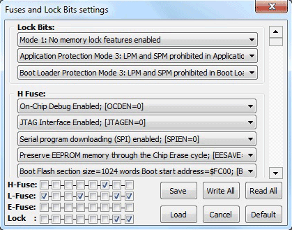
Khazama works with all popular AVR microcontrollers, allows you to program flash and eeprom, read the contents of flash and eeprom memory, erase the chip, and change the configuration of fuse bits (Fuses and Lock Bits). Everything you need to flash AVR microcontrollers. The fuses are configured by selecting the clock source from the drop-down list, thus, the probability of “killing” the controller by mistake is sharply reduced. Fuses can also be changed by placing checkboxes in the lower field, while you cannot checkmark a non-existent configuration, which makes the fuse configuration safer. And this is also a big plus.
Recording Fuses
 The fuses are written to the microcontroller memory by pressing the Write All button. There is a Save button to save the current configuration, and Load returns the saved one. The Default button is for writing a standard fuse configuration, such as the microcontrollers come from the factory, usually 1MHz from the internal RC.
In general, for the entire time of using this programmer, it showed itself from the best side in terms of stability, security and speed. I recommend using it to anyone who wants to program AVR microcontrollers.
A small program created for the purpose of fast flashing Atmel microcontrollers AVR.
The Khazama AVR Programmer application has a simple and user-friendly minimalistic window interface. This programmer is a graphical shell of the avrdude program and is great for novice developers. Khazama AVR Programmer currently supports about eighty AVR microcontroller models belonging to the ATmega, ATxmega, ATtiny and AT90 families. The programmer has a minimum number of functions, but compares favorably with speed and stability. Software allows you to: load into the buffer saved hex-files of the firmware for EEPROM and FLASH memory, write hex files to the EEPROM and FLASH memory of the microcontroller, view the contents of the EEPROM and FLASH memory of the chip, clear the controller memory, change the configuration of FUSE and LOCK bits, verify the EEPROM and FLASH memory. All operations can be carried out either using the menu or using the buttons on the toolbar, appearance which are copied from similar buttons in the software.

Among other features of the Khazama AVR Programmer program, it is worth noting: the presence of contextual tips and shortcut keys, the ability to install this application on top of all other windows, the presence of an EEPROM and FLASH hex-file viewer (without editing), visualization and decoding of microcontroller configuration bit values. Customizable "AutoProgram" button launches a set of operations specified in the "Program Options" window (clearing the chip and writing to FLASH memory is set by default). Khazama AVR Programmer works with TPI programming. The ISP programming clock is adjustable from 500 Hz to 1.5 MHz.
The procedure for programming FUSE bits does not require hexadecimal values and consists in selecting the necessary parameters from drop-down lists, which reduces the likelihood of locking microcontrollers by mistake. Also, FUSE bits can be changed by checking the checkboxes in the lower field. At the same time, it is impossible to check non-existent configurations, which is also a plus in terms of security. The FUSE bit programming window contains the following functions: writing fuses to the controller memory, saving the current configuration to the buffer, calling the saved configuration from the buffer, restoring the standard FUSE bit configuration, that is, the one with which the microcontroller came from the factory. Khazama AVR Programmer works with *.hex memory dump files.
The application was written by an Arabic programmer named Behzad Khazama (Iran, Khorasan-Rezavi province, Sebzevar city). latest version of this programmer was released in mid-2011.
The program is only available on English language and has no cracker.
Khazama AVR Programmer software is supported by operating systems of the family Microsoft Windows– XP, Vista, 7, 8 (32-bit and 64-bit).
Distribution of the program: free
The programmer is based on the Objective Development driver and is fully compatible with the original ATMEL AVR910 programmer. Description of the device. The fuse protects the power lines USB port from accidental short circuits in the power supply circuits of the programmer. Diodes VD1, VD2 are silicon rectifiers, they are designed to lower the power supply of the microcontroller to 3.6 V. According to the documentation, the controller can operate at this supply voltage up to a frequency of just over 14 MHz. LEDs VL1 (" RD"), VL2(" WR”) signal the current actions of the programmer and indicate the read and write modes. LED VL3 (" PWR”) indicates that power is being supplied to .
Jumper J1 - ( MODify) serves for the initial programming of the control MK programmer. When it is closed, an external programmer is connected to the ISP connector and the control program is loaded into the MK. After programming the control MK programmer, this jumper must be opened and the jumper J2 - NORMal closed.
Jumper J3 LOW SCK lowers the clock frequency of the SPI port of the MK programmer to ~ 20 kHz. When the jumper is open, the SPI frequency is normal, when the jumper is closed, it is reduced. You can switch the jumper on the go, since the programmer's MK control program checks the status of the PB0 line each time the SPI port is accessed. It is not recommended to switch the jumper while the process of writing/reading of the programmable MK is running, because, most likely, this will lead to distortion of the written/read data. Jumper J3 is introduced for the possibility of programming MK AVR, clocked from an internal 128 kHz generator.
Resistors R10 - R14 are designed to match the signal levels of the microcontroller of the programmer and external circuits (programmable MK or other programmer). The clock frequency of the SPI port of the MK programmer with the open jumper J3 is 187.5 kHz. This allows the controllers to be programmed with clock frequency from about 570 kHz for ATtiny/ATmega, 750 kHz for 90S and 7.5 MHz for 89S. Controllers are programmed from 10 to 30 seconds (using the AVRProg v.1.4 utility from the AVR Studio package) along with verification, depending on the amount of FLASH memory and clock frequency.

A square wave with a frequency of 1 MHz is output to the LED output of the ISP connector to "revive" the MK, which had erroneously programmed fuse bits responsible for clocking. The signal is generated constantly and does not depend on the operating mode of the programmer. The programmer was tested with the programs AVRProg v.1.4 (included in the AVRStudio package), ChipBlasterAVR v.1.07 Evaluation, CodeVisionAVR, AVROSP (ATMEL AVR Open Source Programmer). For the normal functioning of the controller in the circuit, it is necessary that the bits be programmed (set to "0"). SPIEN, CKOPT, SUT0 and BODEN. Usually microcontrollers coming from the factory, i.e. new, have already programmed bit SPIEN. The remaining bits must be unprogrammed (set to "1").
Instructions for installation and operation. Flash the controller. Connect the freshly baked programmer to the computer via USB. Operating system will find a new device - AVR910 USB Programmer, when prompted to automatically find the driver, refuse, and specify the path to the inf file, depending on the operating system installed on your computer.

The forum contains all the files, as well as the printed circuit board for our avr programmer. Here I will show the technology of assembling the AVR USB programmer and packing it into the case. First, download the archive and make a printed circuit board.

Then we solder all the details on it. I could not find a small quartz, so I soldered a large one, but on long legs, so that later I could bend it so that it would not interfere when installing the board into the case. Next, we select a suitable case, I had it ready.

We adjust the board to the case, make all the measurements, drill holes and here is the finished device for you, with a universal board.

If there is no special measuring equipment, you can check using the LED. The LED is connected anode to the LED pin, cathode to any GND pin of the ISP connector. When power is applied, the LED should glow in the “half-light”. When the legs of the quartz oscillator are closed with tweezers, the LED should either light up in “full heat”, or there should be no glow.

An assembled programmer with a correctly programmed microcontroller does not need to be configured without errors. But if the RESET input of the programmable MK is pulled up to the supply voltage by a resistor, then the resistor value should not be lower than 10 kOhm - this is due to the reduced supply voltage of the control controller in the programmer circuit and the introduction of limiting resistors on the ISP connector bus.
Discuss the article PROGRAMMER AVR USB